Article
- Introduction
- The bike generator
- The art of pedal power: what are the challenges?
- The dashboard: how to address these challenges?
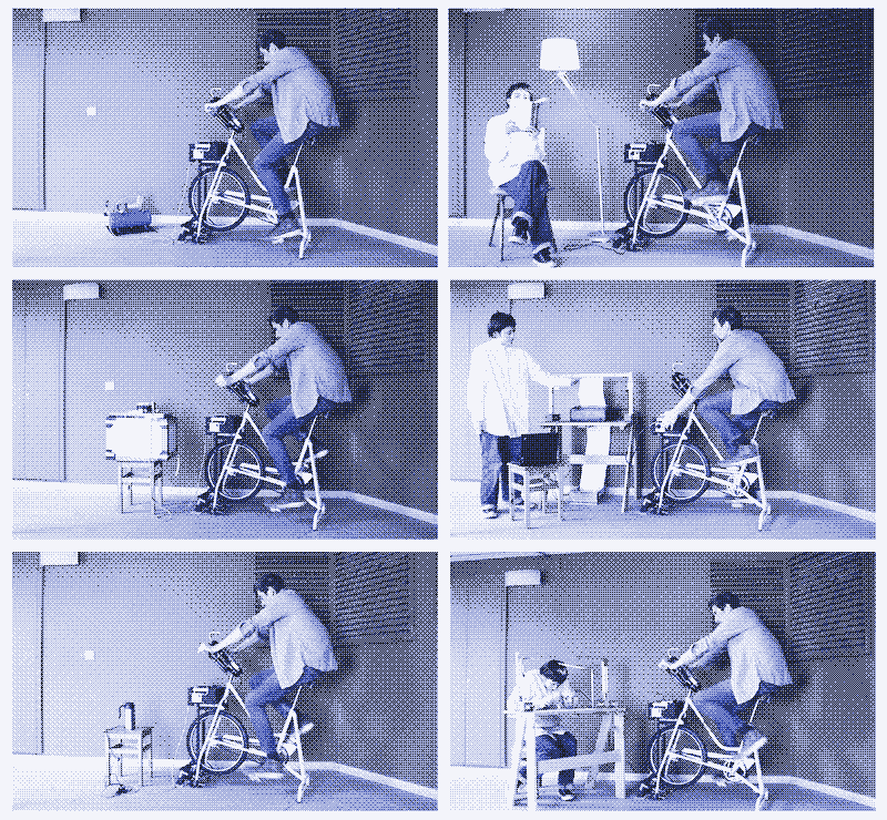
- How to use the bike: experiments
- Alternative configurations: Bike generator with a work table
- Hybrid human/solar power system
Manual
Introduction
Summary
Many people have built pedal power generators and published the manuals online and in books. However, when we set out to make a pedal power generator ourselves, we found that these manuals are incomplete when making the bike generator practical to use. The focus is on building the power source itself, with comparatively little attention to what happens with the power that comes out of it.
To try and make human power production more useful, we built not just a pedal power generator but also a control panel in the form of a “dashboard” attached to the handlebars. The dashboard allows powering or charging a wide diversity of devices – no matter what voltage they run on. Furthermore, multiple devices can be powered simultaneously, allowing the cyclist to adjust the resistance on the pedals for an optimal workout.
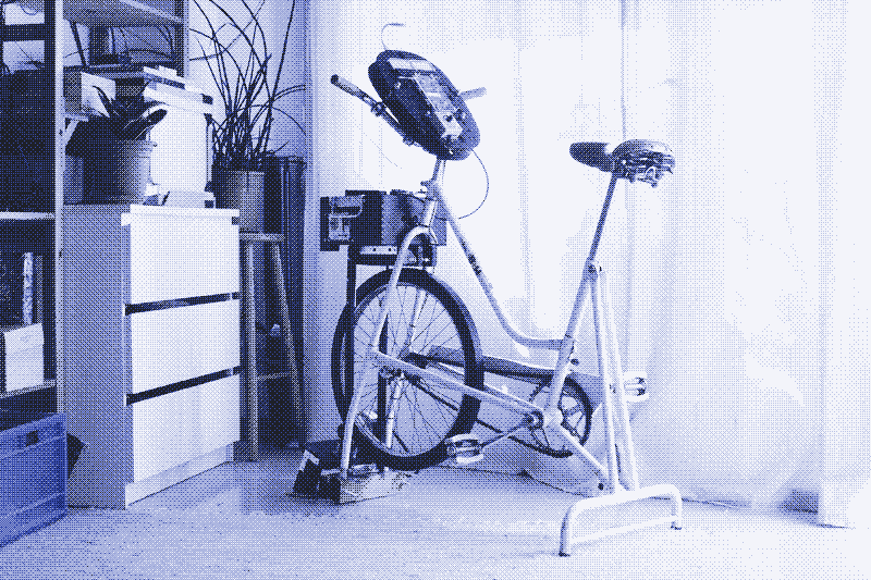
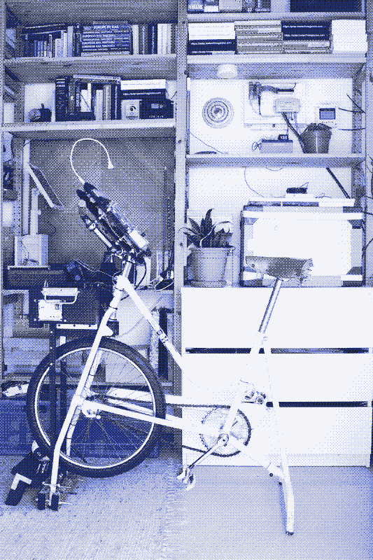
We also tried to improve the bike generator itself. Although there are good manuals available, we wanted a power source that is easy to build (no welding or complex tools required), comfortable to pedal, as compact as possible, and not an eyesore. The bike generator is set up in a small living room and used regularly. We found the solution in a vintage exercise bike with a flywheel, an approach we have not seen before.
Trial and Error
The bike generator and dashboard were designed and made in collaboration with Marie Verdeil as part of her internship at Low-tech Magazine. We could not find the technical information we were looking for, so we followed a trial-and-error approach. That was time-consuming and costly, but we gained insight and learned lessons. We made lots of mistakes that you can avoid.
We are not engineers, and we welcome technical feedback concerning further improvements. Based on that feedback and more experiments with the bike generator – which is now in use for one month – we will update and expand the manual. Our design can be adjusted and adapted to your needs. We appreciate a donation if you find our work interesting. Your support makes it possible to finance further experiments and building projects that we have in mind. Marie Verdeil will continue working with Low-tech Magazine when she finishes her studies at the Design Academy Eindhoven later this year.
Newcomers to this website may want to read some earlier articles that this bike generator project is building further upon: The short history of pedal powered machines (2011), Pedal powered farms and factories: the forgotten future of the stationary bicycle (2011), Bike generators are not sustainable (2011), How to go off-grid in your apartment (2016), Slow electricity: the return of DC Power? (2016), Could we run modern society on human power alone? (2017), and How much energy do we need?(2018).
The Bike Generator
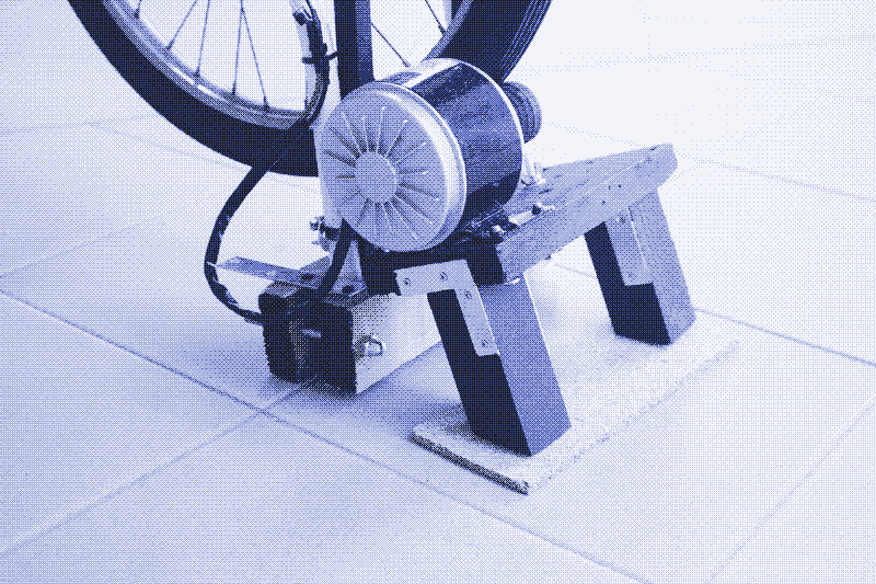
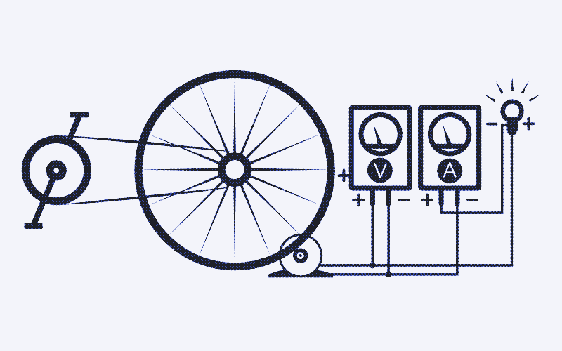
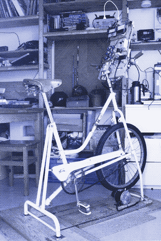
There are many ways to build a bicycle generator, and each has its advantages and disadvantages. We based our pedal power plant on a vintage exercise bicycle from the 1950s. Our bike was made by Spanish brand BH but similar vintage models can be found anywhere in the industrialised world.
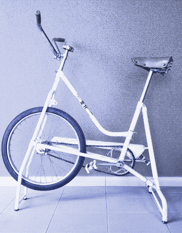
The Flywheel
Our approach has several advantages. The first and most important is that old exercise bikes have a large flywheel in front. Bike generators without flywheels – which are the majority these days – are likely to end up gathering dust in the garage because they are tiring and uncomfortable to pedal.
A flywheel is essential because pedalling a stationary bicycle is a different experience from riding a bike on the road. The power that our feet put on the pedals peaks every 180 degrees of crank rotation. On the road, this has little effect because of the inertia of the cyclist.
In contrast, on a stationary bike, this uneven power output results in jerky motion and additional stress on parts. The flywheel solves this by its large mass and rotational speed. It evens out the difference between power peaks and makes for comfortable pedalling. The rider tires less quickly and can generate more energy. A flywheel also produces a more steady voltage.
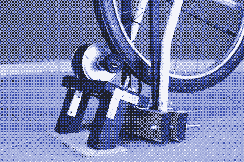
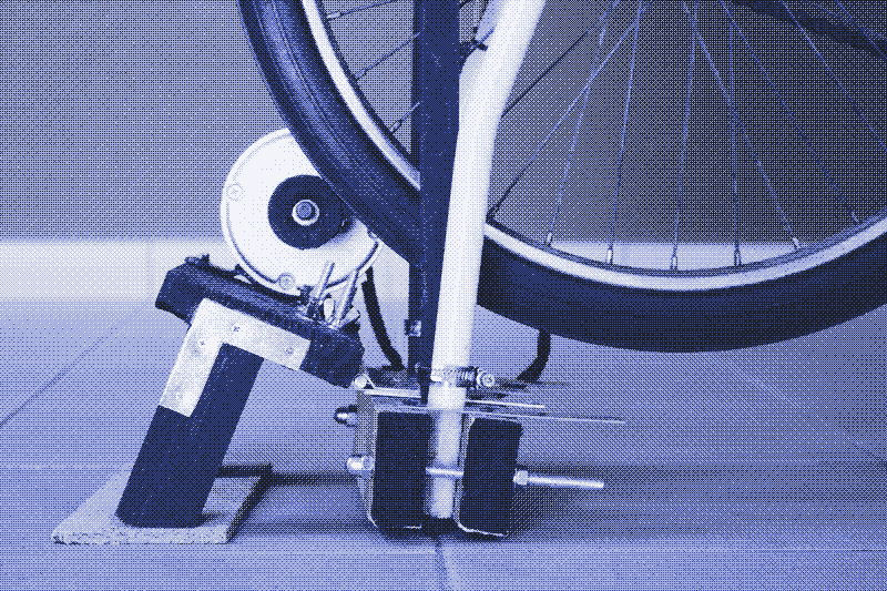
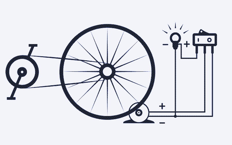
Our approach also makes it possible to build a pedal power generator with simple tools and basic skills. There is no need to cut or weld metal – the bike remains like it is. 1 Neither is there a need to build a support structure – the bicycle already has one. We only had to add a so-called friction drive – a small roller attached to the generator shaft and pressed against the flywheel.
Our method also results in a very compact bike generator. It is just over 1m long. Finally, and although this is a matter of personal taste, it results in a bike generator that is beautiful to behold. The bicycle was bought from someone in a neighbouring village who had it standing in the living room as a decoration.
As a disadvantage, one could mention that a friction drive is less energy efficient than a gear or belt drive. However, the higher efficiency of the flywheel compensates for that. Only a combination of flywheel and gear or belt drive would do better – but that would be more difficult to build. Another disadvantage is that our machine has no switchable gears – more on that later.
Maximum Power Production
The power output (W) of a bike generator corresponds to the voltage (V) multiplied by the current (A). We obtained roughly 100 watts (12V, 8-9A) of power during a short and heavy workout. During a moderate effort – which we can sustain for a longer time – power production is between 45 and 75 watts. The power output not only depends on the bike but also on the person who operates it. Athletes could produce more power, while couch potatoes would (initially!) generate less. 2 3
We measured the power output right after the generator. However, you need to put more power on the pedals to obtain that power output. To start with, no generator is 100% efficient. Our generator achieves its maximum efficiency (75-78%) at a power output of more than 6A (72W). Efficiency decreases when you produce less power: it drops to 60% at 3A and less than 45% at 2A. Second, there are energy losses in the drive train between the pedals and the generator. We cannot measure these, but according to the data we found, a friction drive introduces on average 15% of extra energy losses.
Taking into account efficiency losses in both generator and friction drive, you need to put at least 150 watts on the pedals to obtain a power output of 100 watts. There are additional energy losses in the bicycle drive train. In theory, bicycle gears have low energy losses, at most a few percent. In practice, however, these energy losses can be high. We proved this unintentionally. Power production doubled after we thoroughly cleaned and oiled the bicycle train. We made the mistake of cleaning the bike only at the very end. That forced adjustments to the control panel to manage the higher currents that suddenly came through it.
The Art of Pedal Power: What Are the Challenges?
As a power cyclist, you have to match the voltage (V) and the current (A) of the device you are powering or charging. However, this is easier said than done. Electric devices run on different voltages and they have very different power demands. The voltage refers to how fast you pedal and the current to how hard you pedal.
1. Matching the voltage
A bike generator produces low voltage DC power, similar to a solar PV system (12/24V). The voltage output depends on how fast the bike generator spins. The pedalling rate and the gear ratio determine the generator speed. The manual explains in detail how to set up the correct gear ratio. In short, you need to measure the outer diameter of three parts (pedal sprocket, flywheel sprocket, flywheel) and use those data to calculate the correct spindle size for the intended voltage output.
Once you have set the gear ratio, you could produce a lower or a higher voltage by pedalling slower or faster, respectively. That makes it possible to power devices on different voltages. However, assuming your generator provides 12V at average pedalling speed, you would have to pedal in extreme slow motion to produce 5V, and it will be hard to keep your feet at the pedals to provide 24V. Gears would make it easier to vary the voltage output, but our bike has none.
Running an appliance straight from the generator can be a practical solution if it needs roughly 12V. The flywheel helps to maintain a relatively steady voltage output. However, electronic devices and batteries require a precise voltage. Otherwise, they may not work or get damaged. Furthermore, running an appliance straight from the generator prevents you from powering or charging several devices with different voltages simultaneously – which is a solution to the next problem.
2. Matching the current
Electric and electronic devices can have very different power demands – even if they work on the same voltage. Unfortunately, it’s much harder to adjust the current than the voltage. How hard you have to pedal depends entirely on the device you are powering. In some cases, this results in an optimal resistance. More often, the resistance at the pedals is either too low or too high.
At one extreme, resistance on the pedals is almost zero when charging a smartphone or a relatively small lead-acid battery. At the other extreme, resistance on the pedals is too high when powering a kettle or a refrigerator. Some devices have varying current demands. For example, the printer demands between 25 and 70 watts of power, depending on what it’s doing exactly. There are peaks in power demand following startup and between pages, and printing images requires more effort than printing text.
3. Charging batteries
Off-grid solar PV systems often charge lead-acid batteries. Human power does not depend on the weather and the time of day, but it can be practical to store human energy in a battery for future use.
Based on 100 watts of power production, it’s easy to make overly optimistic calculations about the time you need to charge a battery. For example, if it takes 100 watt-hours to charge a battery, you can do that in one hour. Right? Wrong. Even if you could sustain a power output of 100 watts for an hour, the battery limits how much power you can put into it. It’s not possible to do a short workout to charge the battery faster than it allows you to.
Lead-acid batteries charge between 10 and 25% of their maximum capacity – and we obtained 10% for all batteries tested. For large batteries, this is not a problem. Charging one lead-acid car battery (roughly 60-80Ah) requires you to get 85-115 watts out of the generator, which is a heavy workout. A full charge (12V to 13V) will take five hours, not including charge & discharge losses.
However, for smaller lead-acid batteries, the low power demand is problematic. There is little or no resistance on the pedals (so no real workout), it is very inefficient (the generator has high energy losses), and still, it takes as much time as charging a much larger battery. For example, recharging a 12V battery with a storage capacity of 14Ah (similar to the one powering the solar-powered website) requires only 1.4A. That is not much of a workout (20W).
The same problem occurs with USB devices. The most cited use of a pedal power generator is charging a smartphone. However, recharging a smartphone requires very little power (5-10W) compared to what the bike can produce. (Some newer models allow faster charging). You may think charging a 10Wh phone battery would take only 6 minutes at a maximum power output of 100W, but it takes just as long as when you plug it into a wall socket. A much smaller hand-powered charger would be sufficient to charge a smartphone, but then you don’t have your hands free.
The Dashboard: How to Address These Challenges?
To overcome all these problems, we built a control panel that distributes the power from the bike generator into switchable circuits with different voltages for the operation of various devices. You can use these circuits separately or in combination, which allows you to adjust the resistance at the pedals precisely for the optimal workout. You can also control some devices directly by lowering their power demand.
1. Matching the voltage: Buck and boost converters
There is no need to pedal faster or slower to match the voltage of different devices. Instead, you can use buck converters and boost converters - electronic modules that convert a fluctuating voltage input into a steady voltage output.
Buck converters have a higher input voltage than the output voltage (they step down the voltage), while boost converters have a higher output voltage than input voltage (they step up the voltage). You can adjust the output voltage by turning a tiny screw on the module. There’s more information on buck and boost converters in the manual.
2. Matching the current: Switchable circuits & dimmers
You can build one electric circuit using only one buck or boost converter. You can then adjust the voltage by turning the tiny screw every time you power a device that requires a different voltage. However, building multiple switchable circuits with different voltages brings advantages. Not only can you easily switch between different types of appliances without the need for a screwdriver, but you can also adjust the resistance at the pedals by running several circuits simultaneously.
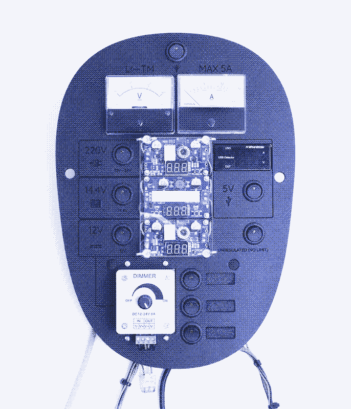
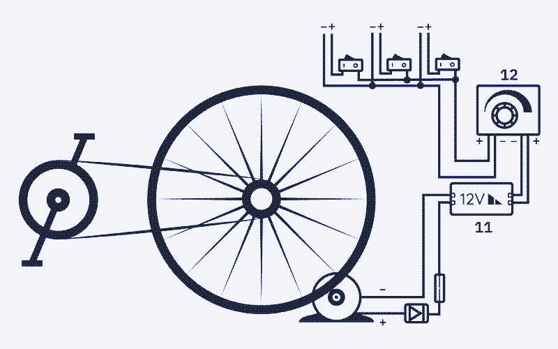
The control panel includes:
- Two circuits for powering or charging USB devices (5V)
- Three circuits for powering 12V appliances
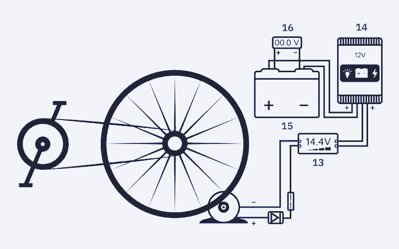
- One circuit for charging lead-acid batteries (14.4V)
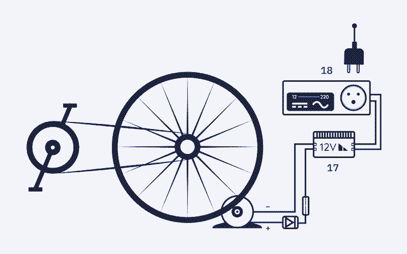
- One circuit for powering mains appliances (220V here in the EU)
- One unregulated circuit where the voltage output matches the voltage input
If there is insufficient power demand, you can increase the resistance on the pedals by switching on more circuits. That will also increase the efficiency of the generator. To address the low power demand of batteries, you can keep the 5V and 14.4V circuits always open. That introduces a basic electric load of roughly 20W (two to five USB devices and a 14Ah lead-acid battery). For a heavier workout, increase the load by opening other circuits and powering more devices. This approach does not shorten the time it takes to charge batteries. However, it makes your effort more worthwhile.
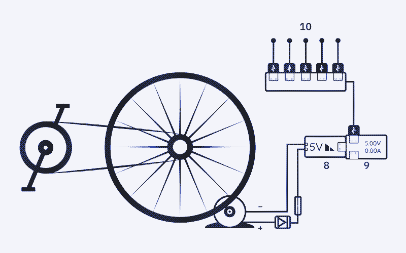
A dashboard with nothing but 5V USB circuits is another option. More so, you use the control panel in that way with small changes. You can hook up a handful of devices to a single USB output, with a maximum power use of 10 watts (5V/2A). Our dashboard has two 5V circuits – one serves primarily for dashboard lighting, but you can add a USB distributor hub to it for another 10W of devices.
You can add six additional USB power outputs by plugging USB connectors into the three 12V outputs, at least when you add three female 12V connectors. That brings total power demand to 80 watts – enough to recharge 10 to 15 smartphones simultaneously. There’s no shortage of USB devices these days: phones, tablets, ebooks, power banks, bicycle lights, cameras, wireless headphones, AA battery chargers, and so on.
Dimmer
If there is too much power demand, you can switch off one or more circuits. For some more powerful 12V devices, the dashboard also allows you to lower the current and thus the resistance on the pedals directly by using a variable resistor or potentiometer (better known as a dimmer).
When you “dim” appliances like the electric kettle or the Peltier refrigerator, they work just as well, only slower. Without a potentiometer, only athletes could power these devices (100-120W). If you plan to charge large lead-acid batteries, you can also add a dimmer to the 14.4V circuit. However, dimming does not work for all devices. A laptop, for example, will shut down if it does not receive the power it needs.
By switching between and combining different circuits - and by finetuning the current on the 12V circuit - you can adjust the resistance at the pedals as precisely as on an exercise bike. That optimizes endurance but also power production.
How to Use the Bike: Experiments
A bike generator is best suited for powering electric devices directly – without storing the energy into a battery first. That avoids charge and discharge losses (up to 30% in lead-acid batteries) and reduces the complexity and the costs of setting up a practical human power plant. For this purpose, the control panel has several 12V circuits and a 220V circuit.
Among the 12V devices that we powered directly are an experimental Peltier refrigerator, a water kettle, laptops – powered by a 12V adapter, and without battery or with the battery at 100% – lights, a soldering iron, a power drill, and a sander. Many more 12V devices exist, mainly aimed at truck drivers and car drivers, sailors, caravan dwellers (and low-tech tinkerers who wire their apartment as if it was a sailboat).
These are all the devices we have powered or charged so far:
- All types of USB devices (5V)
- Lead-acid batteries of different sizes (14.4V)
- Peltier refrigerator (12V)
- Electric kettle (12V)
- Soldering iron (12V) (video)
- Corded power drill (12V)
- Corded sanding machine (12V)
- Air compressor (12V)
- Electric guitar and pedals (220V) (video)
- Cigarette lighter (12V) (video)
- Model railway (12V)
- Sewing machine (220V)
- Dot-matrix printer (220V) (video)
- Stereo amplifier + cd-player (220V)
- Record player (12V) (video)
- Laptops (12V, 220V)
- Lighting (220V) (video)
- Lighting (12V) (video)
- Video projector (12V) (video)
- Fans (5V, 12V, 220V)
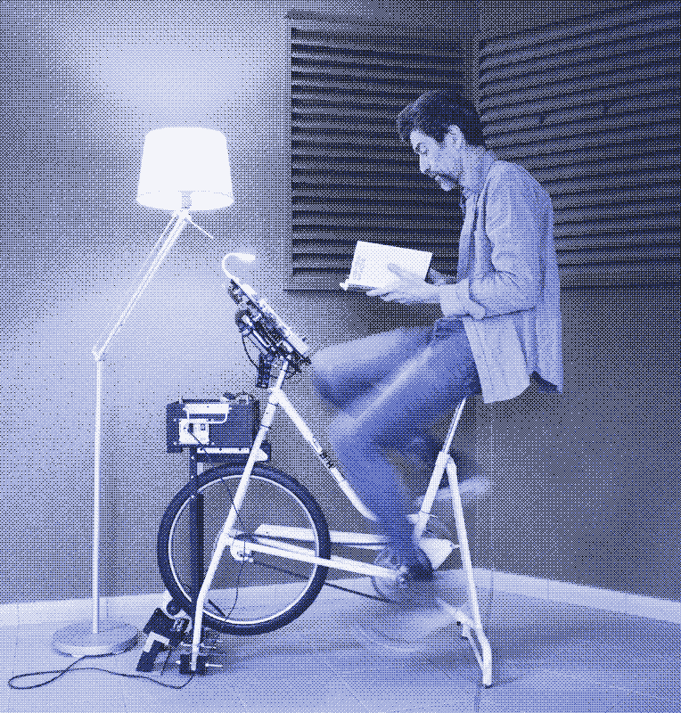
Powering the lights is often more practical with a battery because that allows you to enjoy lighting without having to pedal at the same time. However, it’s perfectly doable to read a book on the bike while providing the lights in real-time, especially in winter – it takes little effort, it’s healthier than sitting still, and it keeps you warm. Other appliances that are well suited for “direct drive” human power production are power tools and heating and cooling devices.
1. Corded Power Tools
Although 12V power tools are widely used, they are almost always powered by lithium-ion batteries. You could recharge these batteries with human power. However, that will take a long time, is not much of a workout, and introduces significant energy losses. Therefore, it makes sense to convert these devices into corded power tools. In this way, you only need to produce power when you need it, with much higher efficiency. Furthermore, there is no more need to wait for batteries to charge – the tool is always ready to use.
Converting a battery-powered tool to a corded tool can be pretty straightforward. After removing the battery, locate the positive and the negative contacts and solder two wires to them. Note that you only get one chance to decide which one is positive or negative. For the power drill, this was very easy to figure out. For the sander, we asked advice because the wiring is more complicated. 12V power tools with missing or dead batteries usually sell cheap on the second-hand market.
A corded power drill is perhaps the most versatile tool. You can use it with a whisk (to beat eggs), a stiff brush (to remove paint or clean objects), a grinding wheel (to sharpen knives), or a polishing wheel (to make chrome or other metals and materials shine). Precision tools for jewelry or model making also combine well with direct pedal power. We are still in the early testing phase for converting and using corded 12V power tools.
Hand vs. Foot-powered Tools
Compared to human-powered mechanical hand tools, human-powered electric equipment is less energy efficient. Going electric introduces extra energy losses – in the generator, the buck converter, the wires, and the drive train. However, this is more than compensated for by a more energy-efficient use of the human power source. Our legs are roughly four times stronger than our arms.
Going electric is also more ergonomic because it spares hand joints and muscles. Fixing dozens of screws by hand may be more sustainable than using a power drill, but it can ruin your wrist. A bike generator thus allows you to work faster and more ergonomically without relying on an external energy source.
Mechanical hand tools keep some advantages: they are silent, more portable, and less energy-intensive to manufacture. A third option combines these advantages: pedal-powered mechanical equipment. However, it’s challenging to build a compact stationary bicycle that can power many different tools. We designed the bike generator to be as compact and multifunctional as possible.
Power tools can have high power demands, but this should not stop you. The sander only needs 30 watts at most, but our power drill can demand up to 20A of current – which is too high for the bicycle generator and control panel (12V×20A=240W). However, the machine will rarely require that power unless you use it to drill through hard materials.
The power demand of a power tool will increase whenever the torque increases, so you feel when the drill bit has gone through the material or when the screw has been fixed or loosened. You can handle the tool as precisely with your feet as you can with your hands.
2. Electric Kettle
Electric heating and cooling are energy-intensive. Alternatives, such as direct solar heat, are more sustainable. However, heating and cooling can easily be included in your exercise routine and provide results.
We apply this principle with an electric kettle and an experimental Peltier refrigerator. Both appliances are very well insulated. Consequently, converting human power into heat or cold becomes another (very cheap and sustainable) form of energy storage – without all the drawbacks of batteries.
Electric kettles that run on grid power are often very powerful and boil water in a matter of minutes or even seconds. Boiling water using a bicycle generator will take a lot more time, but it’s perfectly possible. We acquired a commercial 12V electric kettle with a vacuum insulated reservoir of one litre. During a test, boiling water for one cup of tea took slightly more than one hour at an average power production of 60W.
The electric kettle can also prepare hot water bottles for thermal comfort. That requires more water than a cup of tea, but with a lower temperature of around 60 degrees celsius. During a test, heating one litre of water for a (small) hot water bottle took 1 hour and 30 minutes at an average power production of 60 watts.
Following this effort, the last thing you need is a hot water bottle. Stronger still, during that effort, you are a space heater with an output of several hundreds of watts, and you may be able to increase the air temperature in a small room. However, the vacuum insulated kettle can be put into a fireless cooker and used hours later when you are inactive and need warmth.
3. Peltier Refrigerator
Commercial 12V refrigerators are expensive. After researching thermoelectric generators (TEGs), the idea of a Peltier refrigerator was born. A Peltier refrigerator is essentially a well-insulated fireless cooker with a TEG mounted on top. If power is applied, the module will get hot on one side and cold on the other, cooling the box interior. TEG cooling is not particularly efficient. However, it’s silent, works without problematic cooling gases, and is the easiest way to make a refrigerator yourself.
The TEG refrigerator is an early prototype, which needs further testing and improvements. Powering one TEG at full power requires roughly 60 watts (12V×5A), measured right after the generator. That is a good workout, and the dimmer allows to lower the resistance at the pedals precisely. However, it quickly became apparent that one TEG is not enough for the size of the cooling space. We will add a second one for a heavier workout (60-100 watts).
Mains Appliances (220V)
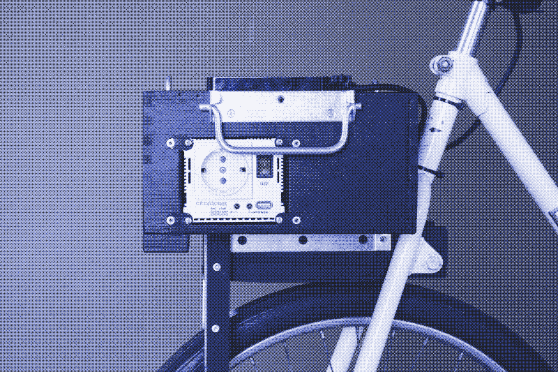
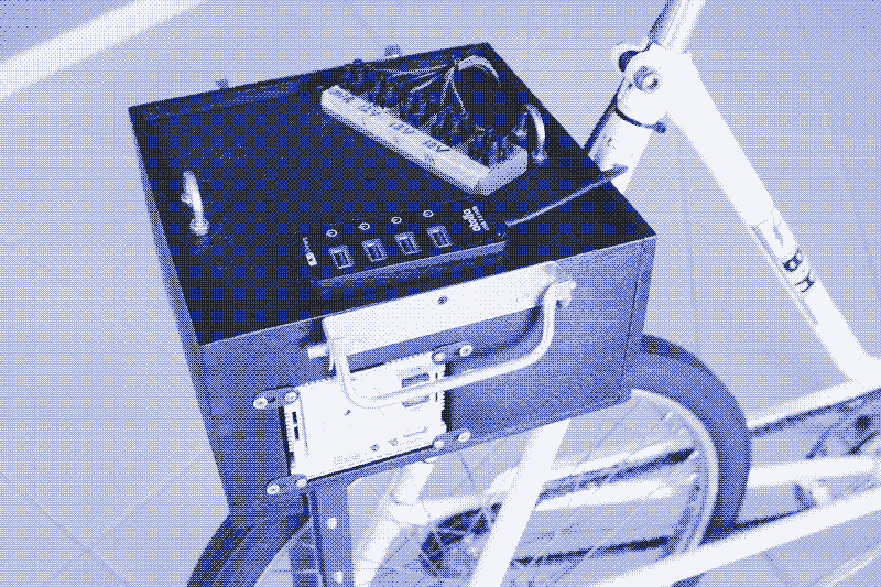
Our dashboard also includes a 220V circuit. That makes it compatible with grid-powered devices (110V in the US, 240V in the UK). The 220V circuit requires an inverter. The inverter is too large to include in the dashboard, so we placed it in a box on the luggage rack that we built in front.
A 220V socket is not necessary. Many 220V appliances have 12V (or 24V) alternatives which are more energy efficient for decentralised power production. However, we included a 220V circuit for powering devices that have not (yet) been replaced by or converted to low voltage alternatives: the dot-matrix printer, the sewing machine, the stereo system, and the router.
The dot-matrix printer and the sewing machine are challenging to operate because of their rapidly changing power demand. For example, to avoid the voltage dropping below 12V at high power peaks while printing, you need to pedal very fast (around 20V) to provide sufficient inertia to the flywheel. A supercapacitor may be able to solve this – this is something we will try in the coming months. A foot-powered mechanical sewing machine and printer would be much more energy-efficient – but much less space-efficient.
Alternative configurations: Bike generator with a work desk
The control panel is designed to power a wide diversity of devices, but you can follow a similar approach with different results. For example, if you only want to charge lead-acid batteries, one 14.4V circuit is enough. You can use a buck and boost converter to create any voltage you need, for example, to build a 3V, 6V, 9V, or 24V circuit.
However, if you mainly want to run 24V appliances, it’s a better idea to adjust the gear ratio. Same if you only want to charge 14.4V lead-acid batteries on a 12V system: adjust the gear ratio to generate 16-17V (to compensate for energy losses in the buck converter).
Our choice to have a large dashboard on the handlebars has advantages and disadvantages. To have the control panel on the bike itself makes it easy to read and manipulate. It also makes the bike generator portable. If the neighbour needs emergency power, you pick up the bike, and you are there in a minute. On the downside, having the dashboard on the bike adds vibrations, which increase noise and energy losses. It also makes it necessary to adjust the voltage output from the buck and boost converters from time to time.
Most importantly, having such a large control panel on the bike prevents you from placing a large desk on top of the handlebars instead. That could be useful to operate power tools or a laptop while simultaneously providing power. Our present set-up is not ideal for using power tools. It requires two people - one to cycle and one to operate the power tool. Likewise, you can power another person’s laptop, but you can’t power yours while using it.
We plan to build a bike generator with a smaller dashboard – one 12V circuit and two USB ports – and a large workspace on the handlebars. Such a bike generator harks back to similar (mechanical) bicycle machines from the early twentieth century. Another option is to screw the control panel to the wall or put it on a shelf – and place the bike generator next to it. The inverter, lead-acid battery, and wind charge controller – now on the “luggage rack” – can also move away from the bike.
Hybrid Solar/Human Power System
Some of you may think that our bike generator is more of a gimmick than a practical power source for the household. In part, this is true. Our human power plant is the perfect exercise machine – power production is motivating. It is also practical in emergencies, especially if enough people power is available – it can produce up to 2.4 kWh per day. However, it won’t provide enough energy daily – not even for a low-tech household. In practice, there are not enough people willing to cycle.
On the other hand, a bike generator is an excellent addition to an off-the-grid solar PV system, at least in a low-energy household. The power output of the bicycle generator does not depend on the weather, the seasons, or the time of day. Human power can provide extra energy during bad weather, which reduces the need for expensive and unsustainable batteries. That is especially useful in winter, when the solar PV system produces much less power, and when the effort required to operate the bike also keeps you warm. There is enough solar power in summer – when it’s often too hot to use a stationary bicycle.
With a power production of 50-100 watts, the bike generator is more powerful than the two solar panels that are standing on the balcony next to it: the 50 watts solar panel that is powering the lights in the living room and the 30 watts solar panel that runs the solar-powered website. The solar panels rarely – if ever – reach their maximum power production, and during bad weather, they produce much less power than the bike generator. With dark clouds overhead, energy production almost drops to zero, and if this lasts for two days, the lights and the website go down. One or two hours per day on the bike generator could fix this. Alternatively, pedal power could operate power tools or other devices without draining the energy storage from the solar PV system.
It’s also possible to use the dashboard with a solar panel instead of a bike generator. It suffices to replace the wind charge controller with a solar charge controller. You can then use solar energy to power devices directly – without necessarily using a solar charge controller and battery. Replace the wind charge controller with a hybrid solar/wind charge controller, and you can use both energy sources to charge batteries and power devices directly. Solar and human power can also be combined, increasing the power output.
Combining solar and human power should make it possible to take further steps towards an off-grid urban household. The plan is to add another 50W solar panel, take more devices off the grid (most notably the refrigerator) and keep the battery storage as it is.
Manual: The Bike Generator
What type of generator do you need?
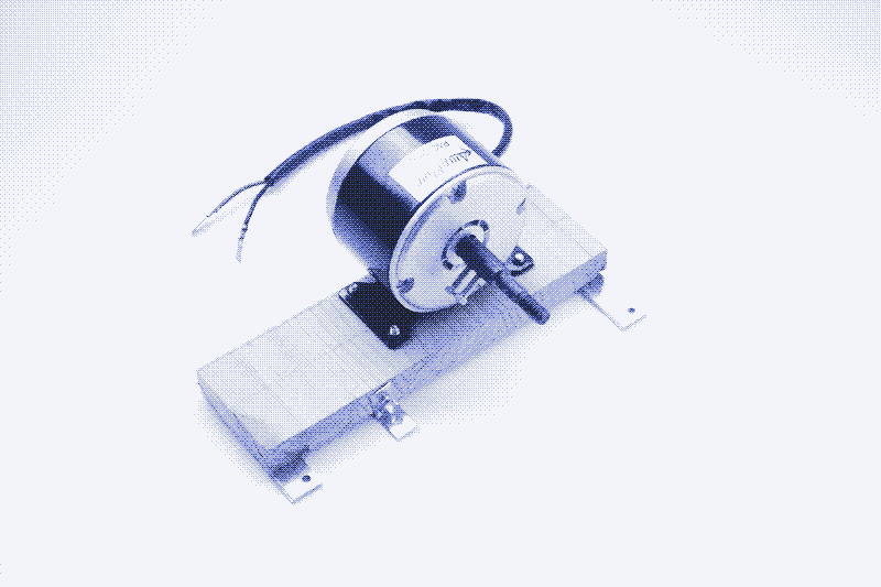
To convert the mechanical energy of the flywheel into electricity, you need a 12V/24V permanent magnet DC generator with a maximum power output of about 150-250 watts. Not any generator will do. You need one that runs at a relatively low speed (<5000 no-load rpm) to obtain 12 or 24V with a practical gear ratio (see further). Many generators need to run at higher speeds to generate 12V or 24V, and you won’t be able to produce more than a few volts at an average pedalling rate.
Be sure to get a brushed DC motor. Brushless DC motors won’t work because they need a very high rotation speed. Note that a generator is a motor working in reverse. When searching online, “DC motor” will give you more results than “DC generator”. Car alternators also work, and many pedal power plants use them because they are cheap and easy to obtain. However, they are very inefficient and require a 9V battery to start.
You can scavenge DC generators from discarded electric scooters or bicycles, but we bought a brand new one: the Ampflow Pancake Motor P40-250. It has a no-load RPM of 1700 at 12V and a maximum power output of 250 watts. You can tighten it securely to a metal or wooden surface, which saves a lot of trouble.
How to calculate the gear ratio and spindle size?
The voltage created by the generator is directly proportional to the rotating speed of the generator (the RPM or “rounds per minute”). However, the rotating speed of the generator is not a given. It depends on how fast you pedal (the RPM of the pedals). It also depends on the gear ratio between the pedals and the generator. The average RPM of the pedals on a stationary bike – a comfortable pedalling rate that you can sustain for a long time – is roughly 60 RPM. It can be calculated precisely by a tachometer or using low-tech tricks. 4
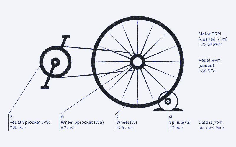
Our bike generator uses a friction drive. It consists of a small wheel (the spindle) attached to the generator shaft that will spin in contact with the flywheel. Calculating the gear ratio involves measuring the outer diameter of four parts: the pedal sprocket, the flywheel sprocket, the flywheel, and the spindle. The first three are known, while the latter was for us to figure out. The spindle size you need depends on the specifications of your generator and on the exact voltage that you would like to produce. Figuring this out can be mind-boggling unless someone provides you with the right formula (thank you, Gabriel Verdeil!).
First, you need to find the “no-load RPM” of your generator. This information should be provided by the manufacturer. Our generator has a no-load RPM of 3400 at 24V. This ratio is proportional – you can calculate the required no-load RPM for any voltage you want. For example, at 12V it’s 1700 RPM (3400/24×12), and at 16V it’s 2267 RPM (3400/24×16). Next, measure the outer diameter of the pedal sprocket, the flywheel sprocket, and the flywheel. Whether you use mm, cm, or any other unit doesn’t matter but be consistent. Now you have all the data you need to calculate the spindle size. Below is the formula, followed by the calculation for our specific case (assuming 60 RPM at the pedals):
Spindle diameter = (PS×W×RPM pedals)/(WS×RPM generator)
- PS = pedal sprocket diameter
- W = flywheel diameter
- RPM pedals = how fast you pedal
- WS = flywheel sprocket diameter
- RPM generator = the no-load RPM of the generator
Spindle diameter for our configuration (in mm) to produce different voltages:
- 12V = (190×525×60)/(60×1700) = 58.68mm spindle diameter.
- 13V = (190×525×60)/(60×1842) = 54.15 mm spindle diameter.
- 14V = (190×525×60)/(60×1983) = 50.30 mm spindle diameter.
- 15V = (190×525×60)/(60×2125) = 46.94 mm spindle diameter.
- 16V = (190×525×60)/(60×2267) = 44.00 mm spindle diameter.
- 17V = (190×525×60)/(60×2408) = 41.42 mm spindle diameter.
- 24V = (190×525×60)/(60×3400) = 29.34 mm spindle diameter.
The exact voltage you need – and thus the exact spindle size – depends on what exactly you want to do with the bike. We address this in detail in the manual for the control panel. Imagine you want to charge lead-acid batteries (which require 14.4V). You use a buck converter (which steps down the input voltage), so you will need to produce close to 17V to make up for the losses in the voltage conversion. That results in a spindle diameter of 41.42mm. This configuration shows in the illustration below.
You can use the formula in different ways. You can use it to calculate the minimum RPM at the pedals for a given spindle; to calculate the generator RPM based on a given RPM at the pedals and spindle size; and to calculate the voltage that will be produced by a given configuration. Find the formulas below, followed by an example based on the configuration illustrated above:
Calculate the minimum RPM at the pedals for a given spindle size (S):
- RPM generator/[(PS×W)/(FS×S] * 2260/[(190×525)/(60×41)] = 55.81 RPM at the pedals.
Calculate the generator RPM for a given spindle size and RPM at the pedals:
- (PS/FS)×(W/S)×RPM at the pedals * (190/60)×(525/41)×55 = 40.61 (gear ratio)×56 = 2274 RPM
Calculate the voltage for a given RPM at the generator:
- Generator RPM×No load RPM ratio * 2274×(3400/24) = 16.1V
What type of spindle do you need?
Figuring out the spindle size is only half of the work. It can be challenging to find a spindle with the correct diameter, made from the required materials, and compatible with the generator shaft. We tried a dozen spindles until we got the right one. A flywheel has a hard surface and requires a soft spindle made of rubber or polyurethane. We found that a solid metal and rubber buffer allowed optimal friction with our flywheel. We took it to a metal workshop where they drilled a 10 mm hole into the piece.

Other options are small solid polyurethane wheels and rubber suspensions. Skate wheels have a larger inside diameter which is not ideal for an 8-10mm shaft. Be careful to choose a material that can handle friction: some plastic tends to heat up and melt. Keep in mind: this is a trial and error process. You won’t get this right from the first time. Another route you could take is to design a custom lathed piece, as is described in magnificientrevolution.org’s tutorial. A universal mounting hub can help attach wheels featuring bolt holes, such as robot wheels.
Buying a DC generator with a pre-installed spindle seems the easiest solution. For example, Pedal Power Generator offers a 360W generator with a spindle size of 37.5 mm. However, you can’t choose a spindle with a different diameter. That means you cannot control the output voltage unless you replace the sprockets in the bicycle drive train. In our case, a 37.5mm spindle would produce 18V, which is too much.
How to fix the spindle to the generator?
The generator comes with an integrated sprocket or pulley drive. You need to remove it to attach the spindle. A nylon lock nut with a reverse tread holds the sprocket or pulley drive. You need to unscrew it to the right. You probably need a clamp to manage this.

Our generator features an 8 mm shaft, while our spindle fits on a 10 mm shaft. Therefore, we use a two-part spindle featuring a “shaft arbor” and a wheel. To properly attach the spindle, you can take advantage of the D-cut on the shaft (a “round shaft with drive flat”). Our first try was a threaded fixation, but that did not work. Because of the reversed thread, it will come loose when the generator starts spinning.
We found that a threaded shaft arbor with set screws was the most versatile solution to test different wheels. We fixed the shaft arbor with grub screws placed on the flat section of the shaft. It’s an M10 threaded rod. You can secure a wheel on it with a couple of washers and a nut. A Bore Rigid Coupling could also serve as a small spindle. You can also use it to attach the generator’s shaft to another axle with a wheel. However, we found this was not ideal for our setup because the set screws stick out of the coupling, damaging the flywheel.
How to fix the friction drive to the bike?
We screwed the generator to a wooden board and then pressed it against the flywheel using a wood support structure. The board is attached to the bike with a strong door hinge. That allows adapting the angle at which the spindle is in contact with the flywheel. The stand is resting on a cork wedge that buffers the vibrations. See our first prototype for another method.
Manual: The Control Panel
Buck and boost converters, dimmers
Buck converters and boost converters are electronic modules that convert a fluctuating voltage input into a steady voltage output. Buck converters have a higher input voltage than the output voltage (they step down the voltage), while boost converters have a higher output voltage than input voltage (they step up the voltage).
You can adjust the output voltage by turning a tiny screw on the module. Some buck and boost converters come with a small digital screen that shows the output voltage. If this is not the case, you can use a multimeter to adjust the voltage output.

Note that you need either a buck or a boost converter. Do NOT use a buck/boost converter. This is a sort of micro bench supply that requires the output voltage to be adjusted every time the system is powered up. This is unpractical and risks damage to your appliances. In contrast, a buck or boost converter remembers the output voltage whenever you start it up.
Also, do NOT buy a voltage regulator. This device allows you to regulate the output voltage but only in relation to the input voltage. If the voltage input changes, so will the voltage output. You want a buck or boost converter, in which the voltage input can fluctuate but the voltage output is stable.
Finally, you should check the maximum current rating before buying a buck or boost converter. Some only take 2A, which is not powerful enough for a bike generator. You need at least one that can take 5A and preferably one that can take 10A or 15A, depending on your power output.
Buck or boost converter?
Whether you opt for a buck or a boost converter depends on the voltage produced by the generator – and by the voltage of the device(s) you want to power or charge. If the bike generator puts out 12V and you want to charge 5V USB devices, you need to step down the volume and thus use a buck converter. These small modules with a USB connector convert a fluctuating voltage input into a steady 5V voltage output. 5
If you want to power 12V devices or recharge lead-acid batteries (14.4V), both a buck and a boost converter could work. If you opt for a buck converter, the bike generator needs to have a voltage output that is slightly above 12V or 14.4V (13-14V and 16-17V, respectively). This higher input voltage is necessary to compensate for energy losses in the power conversion. If you use a boost converter, the voltage output of the generator needs to stay below 12V or 14.4V.
A buck converter will never exceed the chosen voltage output, no matter how many volts the generator produces. In contrast, a boost converter guarantees you a minimum voltage output, but it does not set a maximum output voltage. If you pedal too fast, the voltage output may exceed the set voltage output and damage the appliance or battery you are powering or recharging.
For our first dashboard prototype, we used only buck converters. We used a boost converter to charge lead-acid batteries for the next version. The generator needs to produce 16-17V to obtain a voltage output of 14.4V with a buck converter. That is fine if you only want to charge lead-acid batteries because you can then adjust the gear ratio to produce 16-17V at a comfortable pedalling speed. However, if you optimize the gear ratio for lower voltages, you have to pedal very fast whenever you include the charging of batteries in your workout.
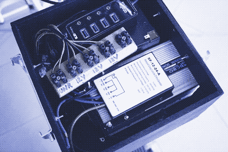
Wind charge controller
The bike generator needs to supply 14.4V to charge lead-acid batteries – the maximum voltage that a lead-acid battery needs. In principle, all you need is a buck or boost converter, but there’s one caveat: you may overcharge the battery, which can lead to an explosion.
You can avoid this risk in a low-tech way – by keeping an eye on the amperemeter. Once the current drops to 3% of the rated storage capacity of the battery (in Ah), the battery is fully recharged – and you should stop pedalling. Because you are the power source and thus certainly present and awake, this approach is less risky than charging a lead-acid battery from a DC power supply or a solar panel without a charge controller.
However, it’s a good idea to add more security. A solar charge controller provides this security in a solar PV system. It cuts the power input whenever the voltage rises above 14.4V. However, a solar charge controller does not work when coupled to a bike generator. Instead, you need a wind charge controller, which operates the other way around.
Instead of cutting the load to zero, a wind charge controller suddenly increases it and “brakes”. If you use a buck converter, the wind charge controller will rarely activate the break because the buck converter will limit the voltage output to 14.4V. It will only brake when you threaten to overcharge the battery. If you use a boost converter, the wind charge controller will brake whenever you accidentally exceed a voltage output of 14.4V.
Wind charge controllers have three green wires to connect to the power source. You can take any two of these three wires and connect them to the plus and the minus of the power input – it doesn’t matter which goes where.
Most wind charge controllers commercially available are way too powerful for a pedal power generator, so get the smallest one you can find. We sent two charge controllers back to the manufacturer. One wind charge controller with a screen came without a manual, and nobody could figure out how it works. The only hybrid wind/solar controller that we tried, for now, was dangerous. The solar panel overcharged the battery. It also maintained the electric brake for half an hour whenever we crossed the threshold, thus blocking human power production.
Wires, Connectors, Diodes, Fuses, On/Off Switches
You need wires, connectors, diodes, fuses, and on-off buttons to connect everything. All these parts can confuse you, so here’s what you need to know.
Wires
The control panel includes roughly ten meters of electric cable. However, the main thing to worry about is not the length but the thickness of the cable. Opt for too thin wires, and your dashboard may catch fire during a heavy workout. Making the right choice can be confusing because there are several standards. We wired the dashboard with a 20AWG 0.52mm2 cable, which takes 11A. A better option would have been an 18AWG 0.82mm2 cable, which takes 16A. Take care when stripping the wires: if you cut too deep the cable can take less current.
Connectors
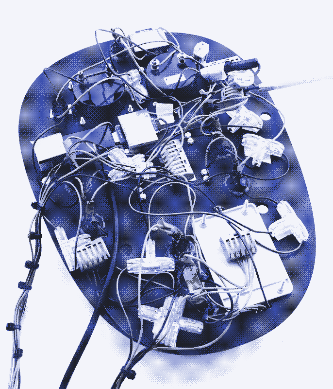
Wires can be connected using very different methods. We choose lever connectors – bulky and expensive but handy. They help to connect wires securely without soldering or screws. These connectors come with two to ten pins. Wiring the dashboard can become disorderly. Make sure you don’t cut the cables too short.
Fuses
You can build a bike generator and controller without fuses, but it’s not a good idea. A fuse will break the electric circuit when you exceed a current threshold, preventing fire and damage to components. We placed a 12A fuse at the entrance of the dashboard (our max power production is 8-9A). We also added fuses to most of the devices we power.
On-off switches
Switchable circuits require on-off buttons. Our dashboard has nine of them. We wanted switches that light up when active because that quickly shows which electric circuits are in operation when starting the pedal power generator. However, lights make wiring the on-off switches more complex.
We bought switches with the wires already attached because we preferred not to solder the connections. However, we had to solder them anyways because the thick wires took too much space. On-off buttons without lights and with prefixed thinner wires simplify this part.
Schottky Diode
A Schottky diode ensures that the current can only flow in one direction through a cable. This tiny part is essential when there are batteries attached to your system. Without a diode, the battery could power the generator (and turn the pedals) instead of the other way around. We put a Schottky diode right after the generator to prevent this. It needs to be rated for the correct amperage: above your expected power production. Our maximum power production is 8-9A, the Schottky diode takes 10A.
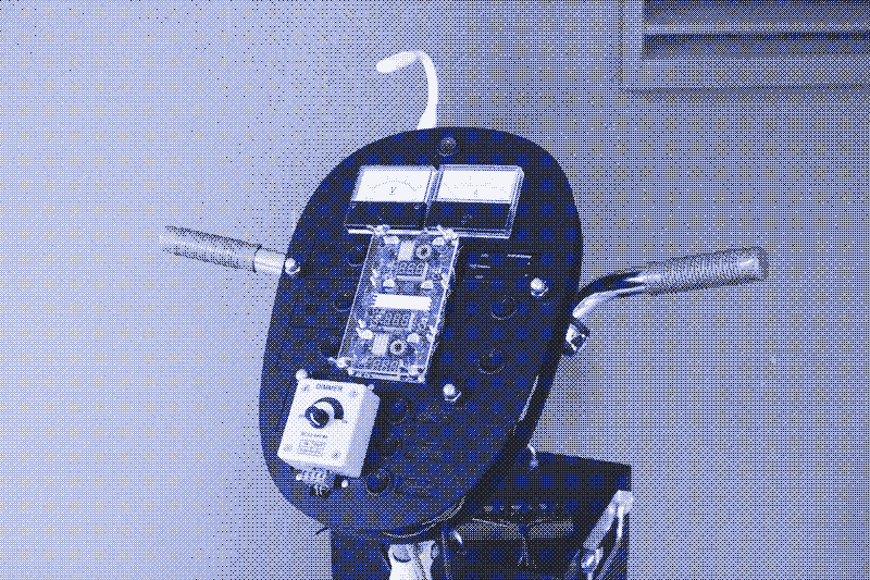
Dashboard Instruments
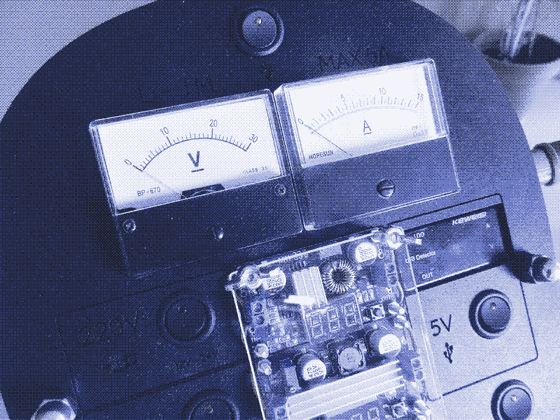
The control panel includes several displays that show the voltage and current in different electric circuits. The analog volt- and amp meter on top is the most important one. It shows how much power the generator is producing (V×A=W). The voltmeter tells you how fast you are pedaling, the amp meter how hard you are pedaling.
Analog V&A meters are most precise in the middle of their range, so we choose a voltmeter that goes up to 30V and an amp meter that goes to 15A. A digital V&A meter is more compact, but analog meters display variations better. Above the meter, there is a USB circuit to plug in a small LED light. That allows you to keep an eye on the V&A meter when dark. It’s also handy to quickly check if the system is working.
Below the V&A meter are three voltage meters for every buck and boost converter. These show the voltage output for each of the circuits. The voltage output should be 12.0V for the 12V and 220V electric circuits and 14.4V for the 14.4V circuit. The first two may fall below that value if you don’t pedal fast enough, while the last one may go above that value if you pedal too quickly – the wind charge controller will also make this clear to you. There is also a voltage and current meter on the 5V circuit. That helps to maximize power production by adding as many USB devices as possible (up to 2A).
Two more instruments are not on the dashboard itself: the voltage meter of the lead-acid battery and the temperature meters of the electric kettle and the Peltier refrigerator. None of these are essential. However, they can motivate the power cyclist. On the road, your efforts result in distance covered. Stationary cycling can be boring – you are not going anywhere. The instruments help you to set goals. For example: let’s get the refrigerator temperature down by 2 degrees C before you take a shower.
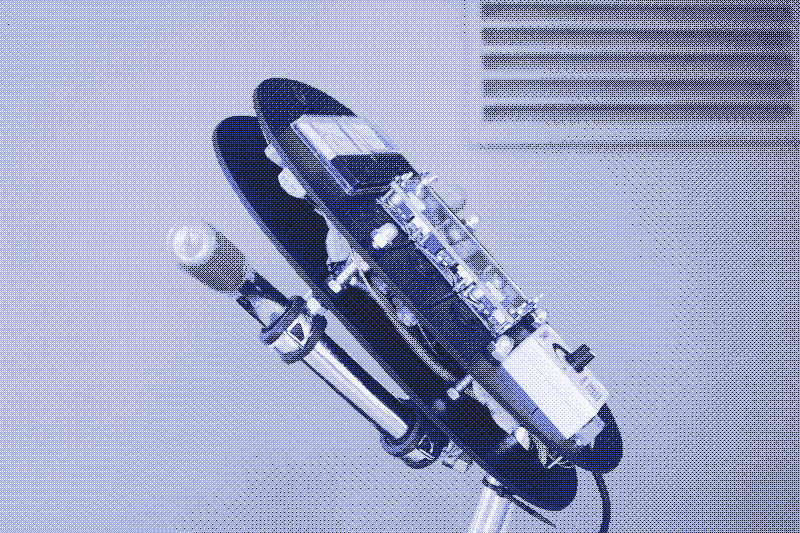
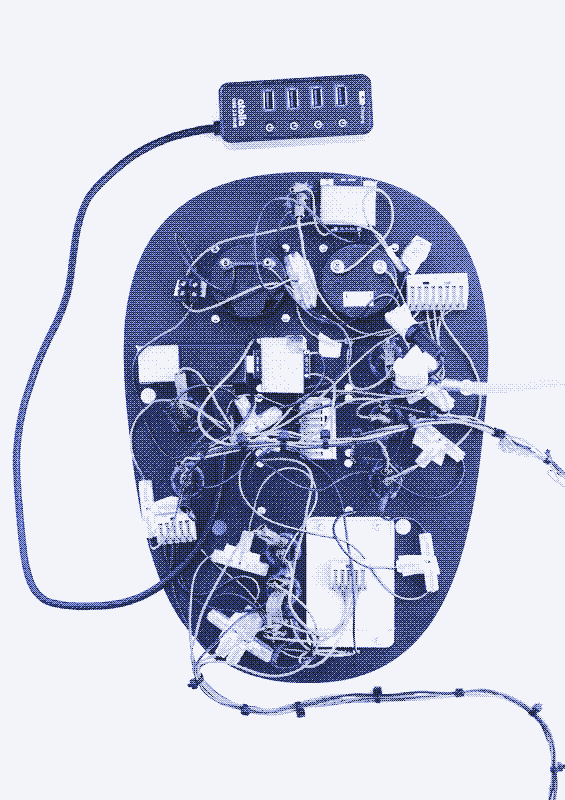
Dashboard Panel and Fixation

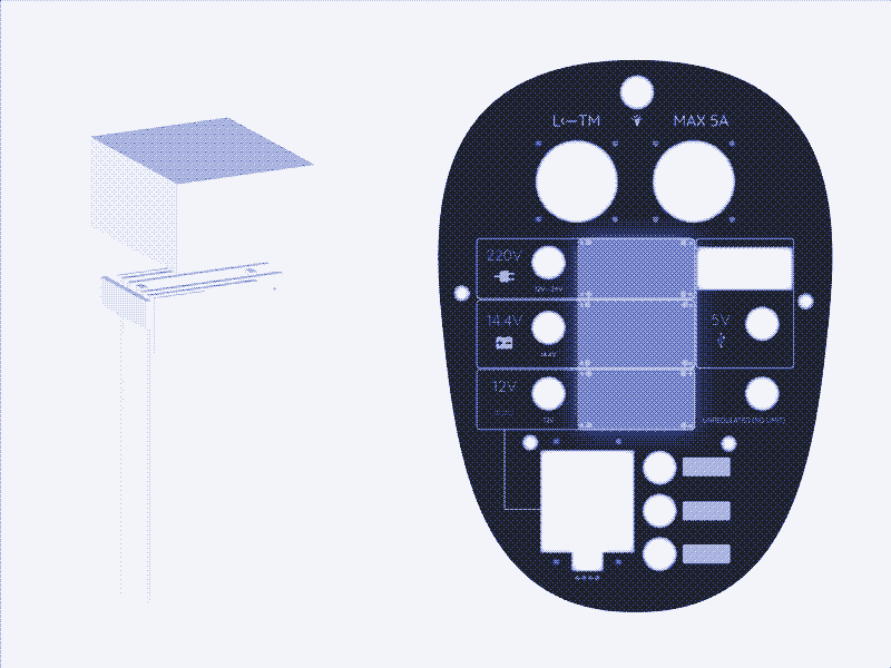
We attached the control panel to the handlebars and added a luggage rack in front that holds extra parts such as an inverter, a wind charge controller, and a lead-acid battery. On top of the box are the power outputs for each circuit and a USB distribution hub. The box has an open lid and holes for the dashboard’s cables to pass through (they first go inside the handlebar).
We used a laser cutter at a maker space (MADE Barcelona) to produce the panel. All components are fitted in or sandwiched between two layers of 4mm MDF. You can easily remove the front panel if something needs to be changed or repaired. A transparent acrylic plate protects the buck and boost converters. You can take it off to adjust the output voltage. We attached the dashboard to the bike handle with rubber pipe clamps, M8 cap nuts, and bolts.
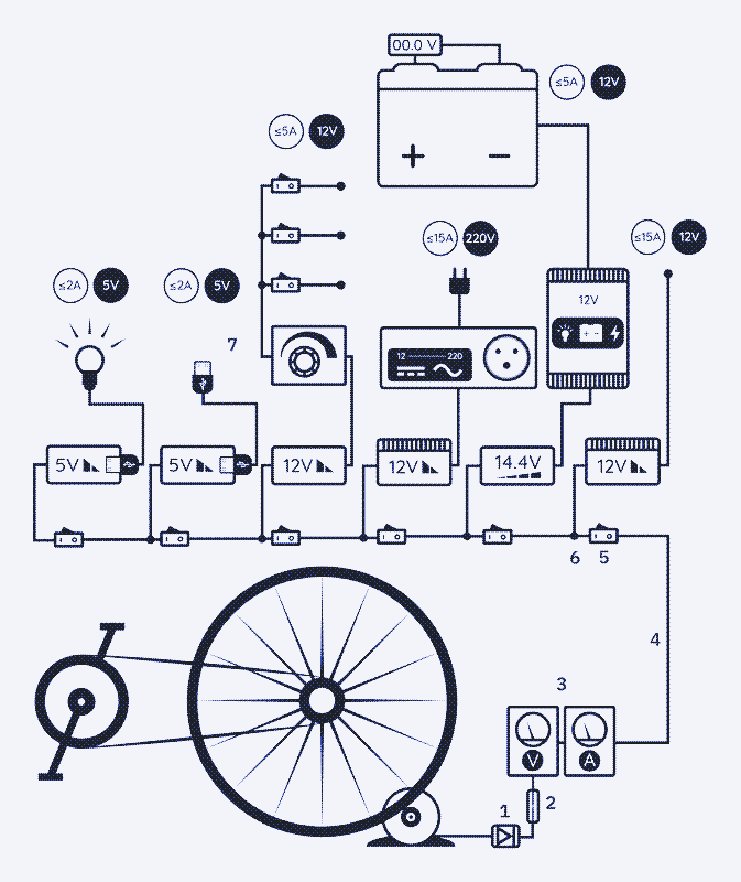
How to Wire the Dashboard?
Complete Control Panel:
5V circuit:
12V circuit:
14.4V circuit:
220V circuit:
Manual: Components List
Generator
- Motor (x1). Ampflow P40 - 250W Pancake DC Brushed Motor 24-12V. 1. Shaft arbor (x1). Threaded Shaft Arbor conversion from 8mm to M10
- Wheel (x1).
Dashboard
- Schottky diode (x1). BOJACK Diode Schottky 10SQ045 (10A 45V)
- Fuse (x1).
- Analog ammeter (x1). Analog Ammeter DH-670 0-5A Class 2.0 & Analog voltmeter (x1) — Analog Voltmeter DH-670 DC 0-30V Class 2.0
- On/Off LED Switch (x8) — KR1-5 Series Rocker ON/OFF Switch 12V 20A 3 pins with LED 1. Wire Connector (≈16 of different formats)
- 5V USB Led Light. Any USB flexible arm LED light will do.
- 5V Buck converter (x2). Buck Converter MH KC24 DC-DC 24-12V Charging Step Down to 5V USB with Fast Charging Protocol.
- 5V USB Voltmeter & Ammeter.
- 5V USB Multi-plug.
- 12 V 5A Buck Converter (x2). Buck Converter DC-DC Adjustable 12-24-36V 5A
- Dimmer & 12V DC Socket (x1). RUIZHI DC 12V waterproof Female Car Cigarette Lighter Socket.
- Boost Converter (x1).
- Wind turbine charge controller (x1) — Asixx Waterproof Wind Charge Controller 24-12V 300/600W.
- Battery Electronic Voltmeter.
- 12V 15A Buck Converter — Buck Converter 200W 15A DC 3-60V to 1-36V step-down adjustable voltage regulator synchronous rectifier module.
- Inverter (x1) — 300W or less Inverter DC 12V to AC 220-240V
- Cable (+10m). 0.52mm2 10M conductor parallel silicon wires 20AWG 11A (10M of each)
Hardware
- M3 Bolts. They fit with the electronic components to secure them to the dashboard.
- M6 Bolts. To attach the motor to the wooden board.
- M8 Bolts. To attach the two parts of the dashboard.
- Big door hinge. To attach the motor at an angle.
- Metal mounting brackets (all sizes and shapes). To strengthen the structure.
- Rubber metal clamps. To attach the dashboard to the bike handle.
- Wood glue, screws (all sizes), bolts, washers and nuts (normal, lock, rounded, wing-shaped), wooden cleats and boards, black acrylic paint, etc.
The Costs
We only include the components we effectively used:
Generator
- Vintage exercise bike (second hand): 60 euro
- Generator: 60 euro
- Arbor shaft: 10 euro
- Spindle: 3 euro
- Total: 133 euro
Dashboard (all circuits)
- Wires: 17 euro
- Connectors: 25 euro
- Analog volt meter: 9 euro
- Analog ampmeter: 9 euro
- On-off buttons: 20 euro
- Diode: 1 euro
- Fuse: 1 euro
- Total: 82 euro
5V circuit
- 5V USB buck converter (2x): 8 euro
- 5V USB V&A meter: 8.50 euro
- USB distribution hub: 30 euro
- Total: 46.5 euro
12V circuit
- 12V 5A buck converter (2x): 24 euro
- 12V 5A boost converter: 8 euro
- 12V 15A buck converter: 25 euro (extra circuit we added later)
- Dimmer: 7.50 euro
- Total: 64.5 euro
14.4V circuit
- Inverter: 50 euro
- Battery (14Ah): 31 euro
- Wind charge controller: 34 euro
- Total: 115 euro
Hardware
- To fix the dashboard and the generator: +/-30 euro
Total cost
- Grand total: 471 euro
Max amperage of all components (circuit limitation):
All components used must sustain the power that goes through it. The voltage is usually not a problem, but you have to watch the amperage. Power production was limited to 60 watts (12V, 5A) – but that was before we thoroughly cleaned and oiled the bike drive train. After cleaning, we discovered the bike could produce almost double that power (12V, 8-9A). That required us to make some updates.
Components get more expensive as their maximum rated amperage increases. For the 12V, 220V, and 14.4V, we stuck to a limit of 5A. Although the bike generator can produce more power, we usually combine several circuits – each limited to 5A. We added an extra 12V circuit with a 15A buck converter and thicker wires to run a more powerful appliance. This circuit bypasses the dashboard entirely. We plan to move this to the unregulated electric circuit on the dashboard (and upgrade the wiring).
- Cables: 11A, 18A for the extra circuit
- USB buck converters: 2A
- 2x Buck converters: 5A
- 1x Buck converter: 15A
- Boost converter: 5A
- On-off switches: 20A
- Diode: 10A
- Fuse: 12A
- Connectors: 20A
Tools you need
- Wire cutter
- Tiny screwdriver (to adjust voltage output on buck and boost converters)
- Calculator, multimeter, tachometer
- Soldering iron. We soldered the on/off switches and the two USB buck converters. However, this can be avoided. Switches can be bought prewired and there are alternative options for the USB converters.
- Wood saw: to make the luggage rack
- Metal saw: to cut custom threaded rods
- Drill: to mount the luggage rack and the dashboard
- Wrench socket set: very handy when working on a bike.
The First Prototype

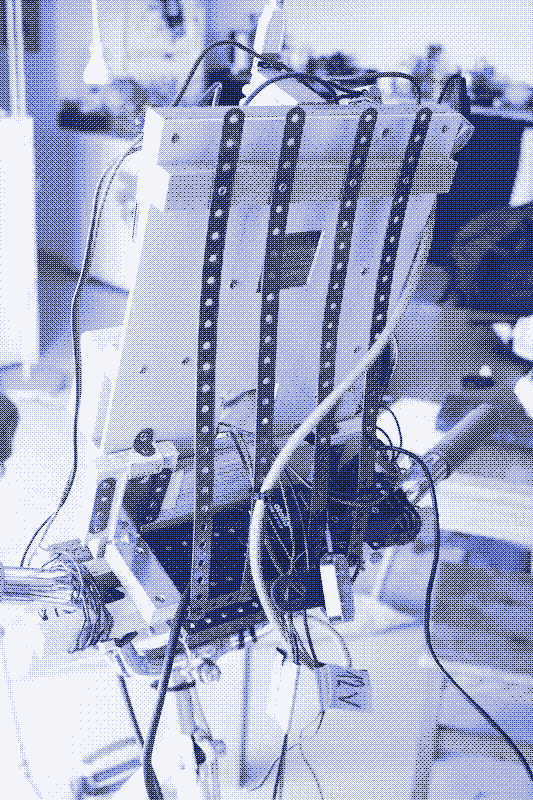
The control panel can take different forms and use other tools and materials. We built a proof of concept with scrap wood and Meccano then strapped it to the handlebars with iron wire and some wooden blocks.
Initially, we screwed the generator on a large wooden board and put the bike on top. We made holes in the board for the four legs so that the bike was always right where it had to be. This set-up worked and was handy to try out different spindle sizes, but it takes much more floor space than our final configuration.
Special thanks to Adriana Parra, Eris Belil, Gabriel Verdeil, and Manvel Arzumanyan.
Reactions
To make a comment, please send an e-mail to solar (at) lowtechmagazine (dot) com. Your e-mail address is not used for other purposes, and will be deleted after the comment is published. If you don’t want your real name to be published, sign the e-mail with the name you want to appear.
Reactions
paul
Interesting proof of concept. I’d like to see this with a belt or chain direct drive (Priority Bikes makes belt drive bikes, as did IKEA at one time, and direct drive bike trainers are growing in popularity) for greater efficiency as you mention at the beginning.
John A Saavedra
Cool! Thanks!
Tony
From that other linked article (“Bike generators are not sustainable”), I got the impression this was thought to be a project not worth doing. Did I read it wrong, or has technology changed sufficiently in the last decade to make it worth doing?
Hemon from Motueka, New Zealand
Nice article thanks for putting the time into researching this. I know it may be counter to your original aims (of making this setup cheap and easy to build), however using an older discarded e-bike would have a brushless electric motor of the right size and kv (speed to voltage) ratings already. If then you spend some time finding a motor controller that was able to do variable regenerative braking (I think the BionX controllers did something like this), this would more easily act as a variable load to the user, and would be very efficient as it would also be able to interface directly with a LiIon battery, which most e-bikes are based on these days.
A drawback to this is the expense and more technologically complex. However the other benefit is that you can use a standard bike and make a frame for it in-side to elevate the rear wheel, so you can still use the bike for transportation and exercise, and energy generation (into the battery) at the same time - increasing its utilisation. The drawback here is that it may not fit nicely in the lounge and may be dirtier, and less practical to have inside.
I think the main aim of a project like this is to manage generation and storage energy efficiencies because of the nature of the limited input power source, ie. the user. Putting more effort into making efficiency gains could dramatically improve the power and energy outputs, enabling the bike to do more with less input effort. The PbA (lead acid) battery that you are using will likely only be at best 60-80% efficient, and the friction drive is great at sucking up energy too. However, it is a great effort and I look forward to your future articles!
Stefan
what fun! a thought…rather than have it below could you hinge the generator/alternator so its weight presses it down onto the flywheel? possibly assisted by a door or gate closing spring?
kris de decker
@ Mike S
Thanks for your advice. Our spindle is indeed wearing out pretty quickly, because the material is too soft. But if we take power directly from the chain, as you suggest, how do we achieve the gear ratio that we need? Also, if we remove the wheel, where do we get the inertia we need?
@ Rudi
Thanks. We did not test the efficiency of the buck and boost converters, but it’s something to consider.
Concerning the charging of lead-acid batteries. Indeed the idea is to rely on the wind charge controller, and let it adjust the voltage as required. Otherwise we would need to fine tune the voltage constantly.
We don’t need to switch all the switches on just to get 5V output, so I guess our diagram is a bit confusing.
Schottky diode: I think you are right and we may just leave it out. We were probably a bit too careful here, the wind charge controller should take care of that.
@ Mathew
I have no idea what is inside the flywheel that makes it so heavy. Sand or water seem unlikely. Could it be concrete? Although it looks like a normal tire from a distance, it surely is not when you take a closer look. It has a very hard surface.
A direct chain drive is surely more efficient, but in that case how do we get sufficient gear ratio and inertia (see also my reply to Mike)?
@ Jonathan
Great advice on the cycling shoes and pedals! That is something we may try out. The aerodynamic wheel cover is also worth a try.
@ Stefan
Pressing the generator down onto the flywheel: I don’t think that would make any difference, and it would be more complicated to build well. The arrangement we have now very easy to make and works very good.
–
Finally, more comments at hackernews: https://news.ycombinator.com/item?id=30589638
Quincy
Howdy,
In the diagram labeled “Complete Control Panel”, I believe labels 3 and 4 are switched.
Thank you very much for another excellent essay, and for exhibiting the true nature of what it means to be human: to share in the experience!
Warmly,
Quincy
Mike S.
Greetings!
I’ve been pedaling my bike for thousands of miles with a generator attached. After much research, I’ve learned a few things that could improve your stationary setup.
Imagine yourself with a budget for power losses. Every loss, measured in Watts, is power that your legs must produce, but you do not get to consume as useful electricity.
By way of mechanical losses, you should consider putting an old cog on your generator shaft, and taking power from the chain instead of the tire. Your current setup will require you to replace the tire every few hundred kilowatt-hours of production! By taking power from the chain, the wear is minimal, and you can power greater loads without slippage. You could also remove the wheel (and its aerodynamic losses) entirely.
Since you’re using a brushed DC generator, the brushes “cost” power in commutation loss as well as friction loss. You would experience greater efficiency with an AC generator (or “alternator”). While automotive alternators are better suited to larger loads, they are often available for free, and would make an interesting experiment.
A “gotcha” of using an AC generator, however, is that an inductive load (like a motor) must be balanced with capacitors for good efficiency. Such a balancing circuit has been designed long ago, and goes under the name “forumslader” (En: Forum Charger) since the design is available for free on a German cycling forum.
I look forward to seeing your future work!
JohnD
Very nice! And LOL to the dot matrix printer : )
Rudi
Hi
I’m a fan of the magazine, discovered it from the solar powered website article, and have been reading it since.
I do software engineering as my job, but I do have a degree in electronics engineering, so I have some insights that might help.
Buck and boost converters:
You mention in the article to go for either buck or boost, but not a buck/boost as it does not keep the output voltage after power cycle. There’s nothing inherent in a buck converter that it would remember the output voltage, and nothing inherent in a buck/boost converter that it would forget it. Maybe most commercial devices operate that way for some reason, but you could definitely have a buck or boost converter that doesn’t remember the voltage after a power cycle, or a buck/boost converter that does.
I also saw something mentioned in the parts list, but not in the article. One of the buck converters are listed as synchronous, but the rest don’t specify. I would definitely suggest using only synchronous switching converters, it takes the efficiency from ~80% to ~90%. Synchronous converters use two switches (usually MOSFETs or something similar), while a basic converter uses a Schottky diode and a switch, and there’s a significant power loss through the Schottky diode. They will be more expensive though, due to the additional switch and complexity.
Charging lead acid batteries:
This is a bit more complicated than what was mentioned in the article. There are two ways to charge a lead acid, float charge, where you’re charging at ~13.5V over a long period of time, and a fast charge, which is a 3-stage charge of constant current, constant voltage, and float. I think the article kind of describes a fast charge, but it’s not doing the constant current part of it (stopping when the current drops low enough). But relying on the wind charge controller should solve the battery charging, but I’m not very familiar with them.
Schottky diode:
It’s correct that you’ll need one to avoid voltage feeding back to the motor, but I’m not 100% sure that its placement is best. By placing it after the generator, you’re sacrificing efficiency. You only really need it for charging the battery, so perhaps better to connect it to the battery so you only have the power loss when charging it, and not when powering the other devices. But in that case, I would expect the wind charge controller to handle that, but I’m not too familiar with them so I can’t say for sure.
Complete control panel wiring diagram:
It looks to me that all the switches in this diagram are wired in series. That seems a bit odd to me, you wouldn’t want to have to switch all the switches on just to get 5V output. It would probably be better to have these in parallel.
Thank you for researching, building, and writing up this guide. I find it very insightful. The use of an old exercise bicycle is very clever, and the insight of just how much power it uses to make a cup of tea is very well illustrated in having to cycle for an hour to heat the water. I never knew about the 12V appliances before, but they make a lot of sense. I used to run the router on a UPS, which is a lead acid battery with an inverter, to be able to have internet during power outages. I’ve recently switched to a li-ion based UPS, that instead has a 12V output to directly power the router, and it’s a lot smaller, quieter, and more efficient (and hence cooler), because it doesn’t need to go from 12V battery to 220V AC, back to 12V for the router. I’m not sure if you have similar products locally, but they do take 12-25V solar input, so they could be a smaller and cheaper alternative to a lead acid battery + wind charge controller: https://sinetechstore.co.za/shop/solar-kits/backup-power-kits/ratel-430s-micro-dc-ups/ .
Regards,
Rudi
Mathew
Kris,
The idea is to replace the flywheel’s hub with one that has sprockets on both sides. You would drive the sprocket on one side of the flywheel (set to a good drive ratio) and pull power from the sprocket on the other side (set to a good generation ratio). These sort of double-sided bicycle wheel hubs are sold as “flip flops.”
Of course, swapping the flywheel’s hub requires either disassembling the existing flywheel or building a new one. It sounds like the heavy, solid tire used for mass may not be removable, and so building up a new flywheel may be required.
Joseph Shupac
Very cool you built this!
I was inspired by past articles you wrote on this topic to try to come up with an idea for a low-tech bicycle that would generate and retain heat (if not from a pedal powered pump, then at least body heat), to allow people to exercise and socialize outside in cold (covid-era) weather.
I wrote a short article about it, maybe you’ll like it:
[https://future-economics.com/2022/03/10/the-warmly-behatted-bike-in-a-box-for-winter-outdoors/](https://future-economics.com/2022/03/10/the-warmly-behatted-bike-in-a-box-for-winter-outdoors/
)
Jonathan
I’m glad to see a comprehensive look into building a bike generator alongside its power management system.
I have a few suggestions to make on the bike side of things. These have a range of feasibility and potential gains, so I will try to order them by decreasing utility.
I had the same thought as Mathew regarding a flip flop hub. It could be an elegant, out-of-the-box solution to connecting two chains to the flywheel, directly driving the DC generator. Depending on the hub, it might even be easy to change the included sprockets, if other gear ratios are desired. This would also not be subject to wearing down the tire and slipping off the generator, two issues Mike S. pointed out. These can be bought as a standalone component or as part of a pre-built wheel.
Cycling shoes and pedals. Stiff-soled cycling shoes transfer more power from a rider’s legs into the pedals of a bike over any other kind of footwear. Using them in conjunction with clipless pedals (which you counter-intuitively clip into) allows a rider to effortlessly maintain their foothold on a bike. Clipless pedals also help a rider maintain a better form while pedalling and crucially, allow for a rider to pedal on the upstroke, not just on the downstroke. Caged pedals are a simpler and cheaper way to accomplish the last two benefits and can work with any (or no) shoes, but have a less secure footing and don’t have the greater power transfer that cycling shoes offer.
I would like to emphasise how this reduces fatigue. Even if other benefits didn’t matter, I can personally attest to how freeing this change is. Without cages or clipless pedals, the rider needs to always apply a little bit of downward force on the upstroke in order to keep the foot on the pedal. In other words, the rider must always be pedalling against themselves in order to keep their feet in place.
I had something here about the seat height before reading the footnotes. Definitely a comfort & fatigue improvement once that part arrives.
This exercise bike is nearing 70 year old, it might be time for a tune-up! As demonstrated with the chain, cleaning load-bearing components could further reduce losses and improve power output of this system. A local bike shop could assess the condition of the bottom bracket, wheel hubs, sprockets (a dirty chain can grind down the teeth), and chain (even with it clean now).
Swapping to bladed spokes. This has contested value on a bike in the “real world” where cross-winds are unpredictable. However, in a controlled indoor environment, the aerodynamic gains in the wheel are consistent and guaranteed, albeit minimal at low RPM. A more effective approach would be to use an aerodynamic wheel cover to entirely encase the rim as is done in velodrome racing.
Unfortunately, as with electronic components, performance is correlated to cost. I hope some of these ideas may be helpful as this project progresses.
Jonathan
P
Hello
Congratulations, I love this project.
Just one thing,I think inertia would be interesting, here you are an example for an increased inertia pedal machine
http://www.mayapedal.org/nut_sheller.pdf
Miquel
Dear Kris De Decker and Marie Verdeil,
Thank you for your research and divulgation.
In your post you talk about the advantages of a flywheel to provide inertia that will give comfort for the rider and constant speed to the generator. Completely agree but I haven’t seen any mention about the importance of the freewheel sprocket as a necessary complement to achieve this comfort and speed smoothness. Some stationary bikes* use a flywheel as a surface to apply friction and a rubber belt for a silent transmission but they don’t have a freewheel sprocket. In consequence, when the rider tries to stop pedalling, the flywheel tries to keep spinning and comfort and efficiency disappears. I suppose your BH stationary bike is equipped with a freewheel sprocket but I think the design I mention can be quite common in the second hand market and probably it would be helpful to provide this detail in the post to avoid some frustrating outcomes.
Regards,
Miquel
As you can see in the provided images
PS 1: the images of the stationary bike are from a similar model to this one: https://es.wallapop.com/item/bicicleta-estatica-antigua-727668727
PS 2: another model than probably have the same design without freewheel sprocket: https://es.wallapop.com/item/bicicleta-estatica-708590359
Tim
Hi, Kris. I’m glad to see you warming up to pedal generators. How you source your build materials makes the difference between being sustainable or not.
As you probably know, eliminating the friction drive is the single largest improvement you can make for energy and material efficiency. I’ve built several of these over the years (all from stuff laying around the house), and by far the most efficient one is my latest. It’s actually just an eBike on a trainer stand, but it is a rare one in that it uses a 36-volt hub motor with regenerative braking (regenerative braking is what enables its use as a generator).
I removed the 36-volt battery and connected the bike’s battery terminals to a 12-volt capacitor, which then feeds my GoalZero Sherpa 100AC. A little bit of searching to find the right gear, but once I do, I can rather easily generate around 40 Watts at 15 volts. My older builds all used some form of friction drive (either wheel-to-wheel or belt), and the best any of them could do was 30 Watts output while working me harder than my latest build does.
Each iteration of friction drive I used had either a belt or tire that would wear. The generators I used also had brushes that would wear out over time. My latest generator has none of that, as it uses a 3-phase AC motor. I don’t need a rectifier, as the bike’s controller passively rectifies the 3-phase motor output to DC.
The GoalZero pack allows me to store 100 Wh, and it can power AC loads up to 100 Watts, USB-A loads, and USB-C loads, including my laptop. A 10-minute ride this morning was enough to charge up my iPhone for the day. Since the chain directly turns the motor/generator, there is no friction drive to wear out or rob power. A combination of the rear wheel and the capacitor smooth the power delivery, allowing the Sherpa’s MPPT input to accurately track the power curve. Pre-existing bicycle maintenance infrastructure will keep the generator going for years to come.
Tim
rob a
Been really excited about this post and doing more research to try to build one myself. Came across Robert Murray-Smith’s video series on youtube. Have you watched any of his videos? Shows how to make a quick easy flywheel, also DIY Kinetic Energy Recovery System and more.
Think you will like them if you haven’t seen them already.
Solrac Z
Excellent article and effort. I have built a bicycle generator that uses my existing bike mounted in a basic bike trainer. I removed the tire from the rear rim used a belt around the rim to turn the generator spindle. I get to use my existing bike with its gears and familiar comfort, I can add weights to the spokes to create a flywheel effect and smooth out the pedal strokes, and with a few minutes effort, can be riding my bike outside.
The most major difference in my generator system is that I used a 15v ultracapacitor to “digest” and regurgitate all of the power that I generate. No need for a regulator as the ultracapacitor takes in unregulated power and discharges it as needed to the powered appliances. The ultracapacitor acts as a sort of “bottomless battery” that spits out power as needed. I am not doing a very good job of explaining how it works, but it takes all of the finicky regulators out of the equation. Here’s a link to David Butcher’s youTube walk through of his power board:
https://www.youtube.com/watch?v=UIxJzprAtc8
I have found this system to be far easier to build and understand than using boost and buck items.
Cavan Mejias
Thanks for the inspiring write-up, I think you guys have taken care of the 99% perspiration for the rest of us.
This YouTube video https://youtu.be/BQt35C5dSCA?t=190 goes over pedal power and invites viewers to take a look at your stationary bike generator.
Keep up the good work and best regards.
J. R. 'Bob' Dobbs
Hi Kris,
Really enjoy your magazine; I think of it as a spiritual successor to the sustainability journal “Whole Earth Catalog” published in the 1970s.
Do you have a tips/submission address for article ideas? I’ve just seen an article on low-tech heat storage at https://www.abc.net.au/news/science/2022-07-19/sand-battery-debuts-in-finland-world-first-heat-thermal-storage/101235514 that looks interesting, particularly if it would be practical at the scale of a typical household or farmstead.
stawy
Good idea. Role division:
Dan S.
In a first place, please excuse the potential english errors that may occure, I am not a native english speaker. Now, because you are measuring the output parameters, maybe you could make an estimation about how much energy (Watts-hour, or hundreds of Wh) could produce a mature man in a day (I dont know, maybe 2 to 3 hours of pedaling the bike discontinuously in my case…). There is already more then 6 months since I’m thiking to build something similar, beginning with the generator (the neodymium N50…N55 magnets are still pretty expensive), but I don’t know exacly how much power a man can provide through the pedals. I know a proffesional bicicle racer can provide about 400W of power for long term (hours), but a average person I think is far away from this value. Anyway, the output power I would like to store it into a powerbank with lithium accumulator cells. Do you think a 200W generator would be to much…? Should I limit to 100W generator? I mean, the output power could be electronicaly adjusted at will (I could build some electronic controllers for this purpose), but I would like to have some kind of starting point, or „landmark” from someone with experience in this field. At the same time I want to loose some weight, in fact I must to do that (I’ve already riched about 220 lbs. from 165, since I got sick). Thank you very much for your time.
Scott B
Very interesting project. As I read through all the instructions for matching loads to the generator it occurred to me that a simpler alternative exists. I was surprised to find that article is dated 2022 since this would have been available then. What I suggest is feeding the output to a commercial power station. Jackery, Bluetti, etc. The solar input generally feeds an MPPT charge controller that I would expect could handle varying input voltages. If necessary, a single boost converter with a 24v output might be desirable. Granted, the power stations are not particularly low tech, but all of the circuitry needed here is rather daunting for a novice. And the price of the smaller capacity power stations is in the range of the costs mentioned for everything beyond the generator itself. The state of charge can be monitored on the display of the power station. And it is already programmed not to overcharge if a solar panel were attached. Finally, many models allow pass through charging allowing you to draw power from the battery while it is being charged.
Could I suggest an followup article? It would be helpful to have plans for a very simple generator that could be built from scrounged components. If we had a SHTF event it would be too late to go looking for most of the parts needed for this project.
Kris De Decker
Thanks for your feedback, Scott. We did not try this, but it is unlikely to work. These power stations contain solar charge controllers, not wind charge controllers. And the latter is what you need for a bike generator. We did connect the bike generator to a standalone solar charge controller, and it doesn’t work. If there would be a power station on the market that includes a wind charge controller, then yes.
Concerning the complexity of the system: there is no need to build all those circuits described in the article above. Usually one or two are enough. We wanted to show all the possibilities in one model. We have built several more bike generators since this one, some of them very simple, built in a few hours.