This manual documents the building of an electric resistance heating element that is directly connected to a solar panel, without a battery, charge controller, or voltage regulator in between. The heating element is used in the insulated solar electric cooker that we describe in another manual, and in the solar-powered coffee maker and foot stove that we will document in forthcoming manuals. Further below, we also describe a method to make a removable heat brick, which we use to replace the commercial heating elements in some earlier electric solar cooker prototypes we made.
A custom-made electric resistance consists of an electric circuit made of nichrome wire, enclosed in a mortar layer. The length and thickness of the nichrome wire determine its current draw at a certain voltage, meaning that you dimension the circuit to your solar panel voltage and power rating to optimize heat generation. The nichrome circuit is connected to the electric cables of the solar panel, with a short section of heat-resistant electric cable in between. 1
Why build an electric resistance heating from scratch?
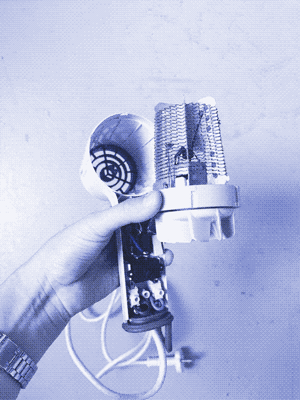
We initially used commercial heating elements in our first solar oven prototypes, which yielded disappointing results. Therefore, we decided to build our own, based on the manual provided by the Living Energy Farm. Building your own heating element involves extra work, but it’s worth the effort. It’s also a lot cheaper.
Many commercial heating elements have built-in thermostats, which can complicate temperature regulation inside the oven. They also require a voltage input that does not align with the voltage output of most solar panels, which introduces the need for an extra electronic component (a buck converter). Securely fixing commercial heating elements proved to be difficult as well, and we had trouble keeping moisture away from the electrical system, which at one point resulted in an electrical fire. By embedding a self-made heating element in a mortar base, we solved all these problems.
What is electric resistance heating?
Electric resistance refers to the difficulty that the flow of electric current encounters when it passes through a material. It’s comparable to friction in mechanical systems. Resistance creates heat, as described by Joule’s Law. Electric resistance is measured in ohms (Ω).
The resistance of a piece of wire depends on its material’s resistivity, but also on its length and thickness. Metals have low electrical resistance, meaning that electricity easily flows through them; they are called “conductors”. For example, electric wires are usually made of copper, which has very low electric resistance.
In contrast, materials such as plastic, rubber, and ceramics have very high electric resistance, meaning that electricity doesn’t flow easily through them. These materials are known as “insulators”. For example, electric wires are encapsulated in plastic, which makes them safe to touch.
Electric heating elements, such as those used in ovens, toasters, and hair dryers, are commonly made of nichrome wire, an alloy of nickel and chromium that has relatively high resistance for a metal. Electrons can pass through, but because they encounter quite some resistance, the nichrome wire dissipates a lot of heat. It glows orange when it heats up.
What you need
In the components list below, we link to Amazon, using it as a global inventory of components. Feel free—and be encouraged—to buy the components locally, or scavenge them from old appliances. We do not earn anything if you purchase on Amazon.
- Nichrome wire. Other example. Nichrome wire is sold in either bobbins or spools. You can also scavenge it from old ovens, toasters, hair driers, and other electric heating devices.
- Heat-resistant electric cable. These electric wires are encapuslated in silicone mesh rather than plastic.
- Thermal switch (optional).
- Thermal fuse (optional).
- Construction mortar for encapsulating the nichrome circuit.
- Thick tiles (in case you build a removable heat brick).
Calculate the resistance value
The challenge in building an electric resistance heating element is determining the correct length of the nichrome circuit to match the voltage and current rating of the power source.
To determine the length of the nichrome circuit, you need to calculate the desired resistance value that corresponds to your power source. You can calculate it using Ohm’s law, which defines the relation between voltage (Volts, V), current (Ampere, A), and resistance (Ohm, Ω):
Resistance (Ω) = U (V) / I (A)
To determine the voltage and current values of your solar panel, refer to the label attached to the back of the panel.
For the voltage, check the “Maximum Power Voltage (Vmax)” or “Voltage at Pmax”. That refers to the maximum voltage that a solar panel can provide when connected to an electric circuit. Ignore the “Voltage Open Circuit (VOC)”, which is the maximum voltage the solar panel produces if nothing is attached to it.
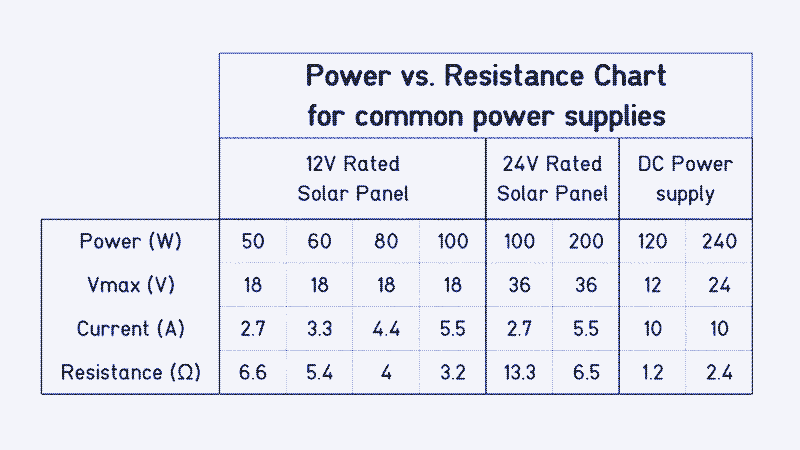
For a so-called 12V solar panel (so-called because it’s typically used in conjunction with a 12V battery and solar charge controller), the Vmax is approximately 18V. For a so-called 24V solar panel (meant to be used in combination with a 24V battery and charge controller), it’s around 36V.
For the current, check the “Maximum Power Current (IMP)” or “Current at Pmax”. Ignore the “Short Circuit Current”. If the label is missing, measure the voltage with a multimeter. You can calculate the current once you know the voltage and power output: electric current equals the power output (100W in our case) divided by the voltage (18V in our case). The maximum current that our 100W solar panel can produce is therefore 5.55 A.
Once you know the voltage and current of your solar panel, you can calculate the desired resistance value for the heating element using Ohm’s Law. In our case:
18 (V) / 5.55 (A) = 3.24 Ω
Calculate the length of the heating wire
The next step is to cut a piece of nichrome wire that has a resistance of 3.24 Ω. Nichrome wire is sold in various thicknesses, each with a different resistance value. The thinner (and longer) a resistive wire is, the higher its resistance will be. The resistance of a nichrome wire is indicated in ohms per distance (for example, Ω/m).
We purchased a relatively thin Nichrome wire with a rated resistance of 8.71 Ω/m. Following the mathematical Rule of Three, based on the resistance per meter, we find that our nichrome circuit needs to be 37.2 cm long to have a resistance value of 3.24 Ω: (100 * 3.24) / 8.71 = 37.2 cm. If you start with a different thickness of Nichrome wire (anything goes), you will obtain a different length.
Don’t trust the labeling
Unfortunately, the resistance value on the nichrome wire packaging isn’t always exact. To obtain a more accurate measurement, cut precisely one metre of nichrome wire and connect it to the solar panel (or to an 18V test station - see further below) with a watt-meter or multimeter in between. Follow the same method when you use scavenged nichrome wire from an appliance.
Connect one end of the wire to the positive output of the solar panel or test station, and the other to the negative output, forming an electric circuit. The polarity doesn’t matter.
Turn the power on, read the amperage and wattage values on your watt meter, and turn it off immediately afterward. Be careful when connecting the wire; make sure it doesn’t touch itself, as this would create a shorter circuit for the electricity. Your measurement will be inaccurate, but it will also draw a lot more current (A) and heat much faster, which can be dangerous. Make sure you don’t touch it either because it gets very hot.
Doing this, we measured 31W at 1.76A and 18V. Based on Ohm’s Law, we calculated that 18 V / 1.76 A = 10.2 Ω. Consequently, our wire has a resistance of 10.2 Ω/m rather than 8.71 Ω/m. That means that it should have a length of 31.7 cm to have a resistance value of 3.24 Ω:
(100 * 3.24) / 10.2 = 31.7 cm.
Doubling or tripling the cable
However, it’s still too early to cut the nichrome wire to size. Depending on the wire’s resistive value that you are starting with, the length that results from your calculation may not be the most practical length for spreading the heat evenly across the surface of your heating or cooking appliance.
For example, the bottom part of our solar oven chamber, right above the electric resistance heating element, measures 26x33 centimeters. With a circuit less than 32 cm long, it’s impossible to heat the oven chamber evenly. A short wire would also create a very warm spot in the mortar and damage it.
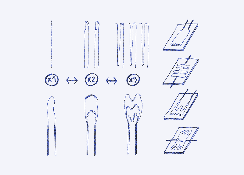
This can be solved by connecting two or more nichrome wires in parallel. If you double the circuit, each wire should be twice as long (63,4 cm each in our case) to keep the same resistance value. If you triple the circuit, each wire should be three times as long (95,1 cm each), and so on.
This may feel counterintuitive, but the longer a cable is, the higher its resistance becomes: electrons will have more difficulty travelling through it. When you double the nichrome cicuit by creating two parallel wires, the electrons can flow in two circuits simultaneously, which means the resitance is halved. Therefore, to keep the same resistance value of 3.24 ohm, you have to make this double circuit twice as long. The same logic applies to a triple wires, where you have to make the circuit three times as long.
Cut the nichrome wire to size
Once you have decided on the number of nichrome circuits, cut the wires to size. However, before you do that, add about 4 cm to every wire. You will need this extra length to solder the nichrome wire to the heat-resistant electric cables (see further).
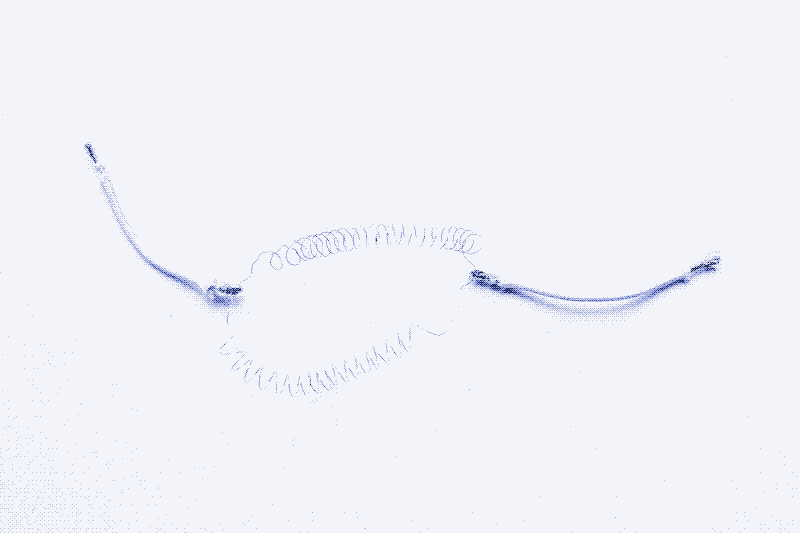
Coiling the wire
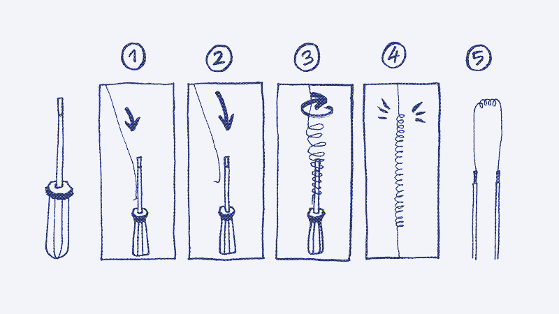
Doubling the circuit, as we did in our solar oven, quadruples the total circuit length. That turns one problem (a too-short cable) into another one (too-long cables). However, it can be solved by coiling the wire, which has an additional advantage: The thin nichrome wire becomes much easier to handle and bend when it’s coiled like a spring. You can do this by wrapping it tightly around a rod-shaped object, such as a pen or a screwdriver. Next, you pull the wire to extend it slightly again.
Thermal switch and fuse
An electric resistance heating element needs a safety precaution to prevent overheating, which could become a fire hazard or crack the mortar enclosure. If the heating element is connected to a solar panel without a battery, as is the case for our solar oven and other appliances, you could argue that it already has a safety precaution: the sun sets every evening, cutting off the power source to the heating element.
However, if you also want to run a heating or cooking appliance on a battery or with a grid-powered test station, you should add a safety precaution that cuts off the heating element if you forget to turn it off.
One way to do that is to add a timer switch. That is a component that controls an electric switch and turns it off after a predetermined time has elapsed. The second approach, which we chose, is to add a thermal switch and a thermal fuse. These components disconnect the circuit when the heating element reaches a certain temperature.
The thermal switch cuts off the heating circuit when its temperature reaches the rated temperature, and turns it back on when the temperature drops below a slightly lower value. The thermal fuse is an extra safety measure: it’s a single-use fuse that blows when it reaches its rated temperature. The thermal fuse should have a higher value than the thermal switch. You embed it in the cement layer, and once it blows, it’s impossible to replace without breaking the oven.
We selected a switch with a maximum temperature rating of 200°C (392°F) and a fuse with a maximum temperature rating of 240°C (464°F). Note that the temperature measured inside the oven chamber will be lower than the temperature of the electric heating element. For example, our thermal switch turns off the circuit at 200°C when the oven chamber is around 120°C (248°F).
You can choose a thermal switch and fuse with a higher temperature. However, we cannot guarantee that the structural materials we used for our oven can withstand higher temperatures than those we use.
Connect the thermal switch and the thermal fuse in series (one after the other) between the nichrome circuit and the positive heat-resistant wire (the one that connects to the positive wire of the solar panel). Ensure the fuse and switch are embedded in the mortar to obtain an accurate temperature reading. Both switch and fuse have no polarity, which means you can connect their pins in either direction.
Solder the nichrome wires to the electric cables
Once the nichrome circuit is cut and coiled, you need to connect it to the electric cables from the solar PV panel. However, you cannot simply solder one to the other: the nichrome wires get hot and would burn the plastic casing of the electric cables. To prevent that, you need to install a pair of heat-resistant electric cables in between.
First, you solder the nichrome wire to the heat-resistance cable. If you want to add a switch and/or fuse (see above), it should go in between the heat-resistant cable and the nichrome wire. Then, you connect the heat-resistant cables to normal electric cables or directly to the solar panel cables (using any type of connector). You also want to put an on-off switch in the positive wire.
In summary, the circuit components should be connected in the following order: positive PV cable, on/off switch, heat-resistant cable, (optional) thermal switch, (optional) thermal fuse, and nichrome circuit.
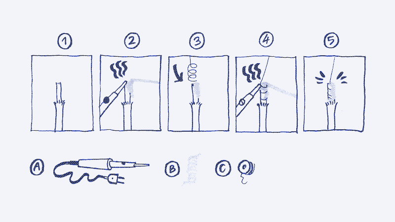
Soldering the nichrome wire to the heat-resistant electric cable is a bit complicated because the nichrome doesn’t stick with tin solder. However, you can get around that problem. Start by applying tin to your stripped heat-resistant electric cable strand (fig2.). Then, coil a few centimeters of the nichrome wire around the cable ends (these are the extra centimeters you added before cutting the nichrome wire to size) (fig 3.). Next, apply a generous amount of tin on top of the twisted wire to trap it onto the cable (fig4.).
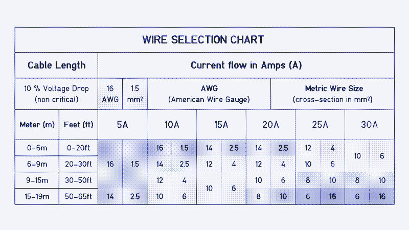
Electric cables come in different thicknesses, measured in mm² in Europe or AWG in the US. The higher the current that flows through it, the thicker an electric cable needs to be. Our circuit works at 5.555A, which requires a 1.5 mm² core wire area. The US equivalent is 16 or 14 AWG. Both the heat-resistant wire and the standard electric cable should follow this size requirement. If you have a different current draw, refer to the chart below to determine the required size. If you plan to use a very long cable between the solar panel and the cooking device, choose a thicker cable.
Encapsulating the heating element
Once the electric resistance heating element is ready, it needs to be encapsulated in mortar, a heat-resistant material with high thermal inertia. We describe two methods for doing that.
1. Encapsulte the heating element in the device itself
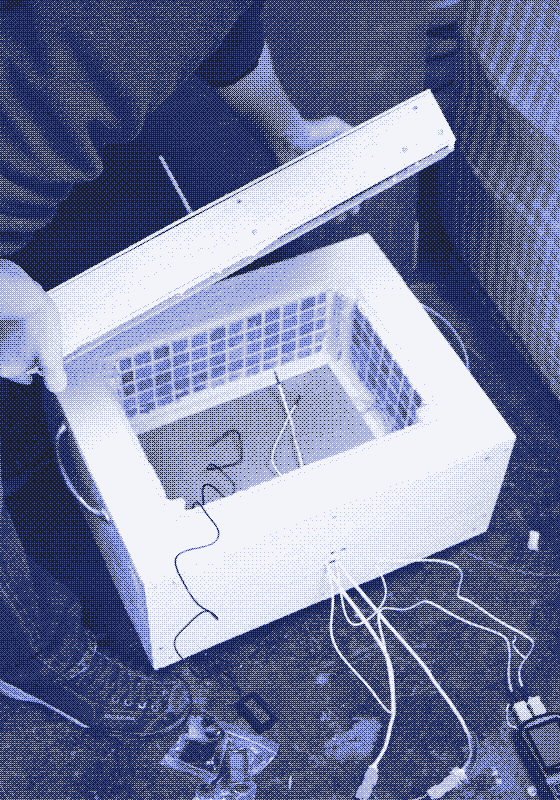
The first method involves encapsulating the nichrome circuit within the structure of a specific cooking or heating appliance. That is how our electric solar oven works: the heating element is embedded into a layer of mortar at the bottom of the cooker, between the insulation layer and the oven chamber (where the food goes). See the manual for the construction steps. The same goes for the coffee maker and the foot stove.
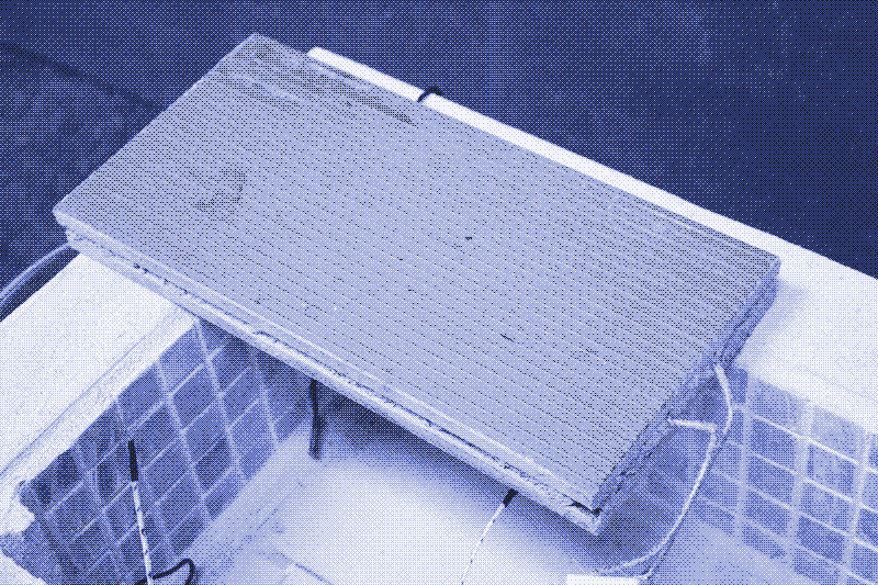
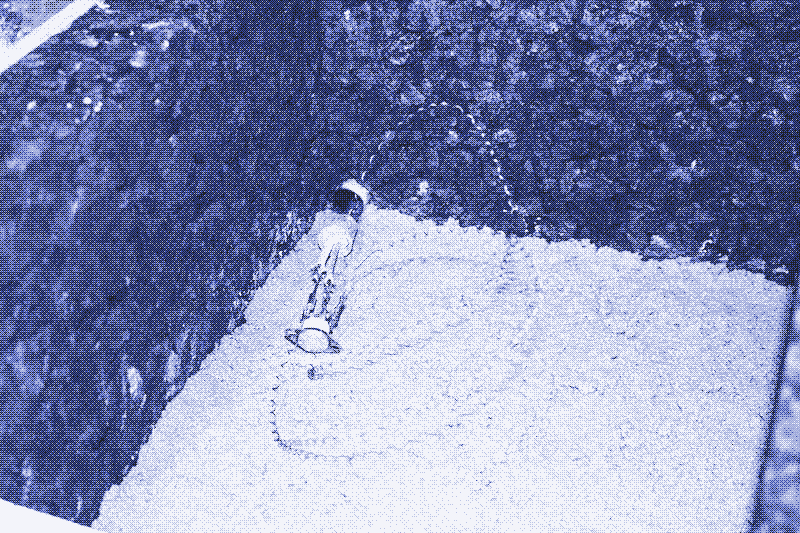
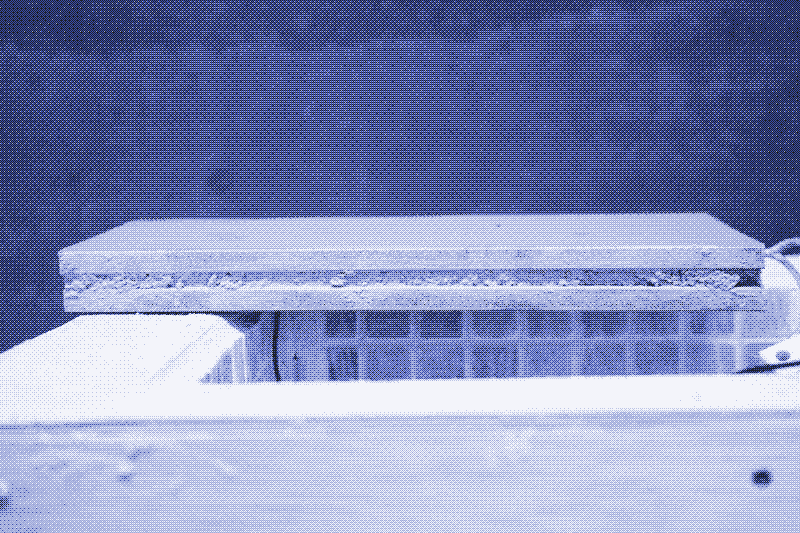
2. Encapsulate the heating element in a removable heat brick
The second method yields a tiled heating brick that can be inserted into various cooking appliances. In this case, the nichrome circuit is embedded in construction mortar and sandwiched between two identical tiles. The two heat-resistant electric cables protrude from one side, ready to be connected to a solar panel. It’s essential to use somewhat thicker and stronger tiles for this purpose, for example, terracotta floor or roof tiles. Thinner tiles may shatter due to the heat.
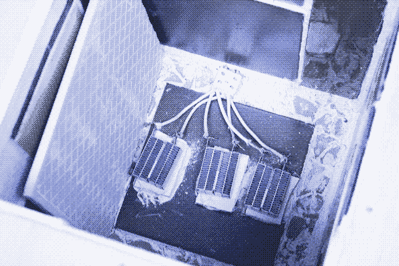
We use these removable heating bricks to power the first two solar oven prototypes that we made. It’s a less energy-efficient method, but if the nichrome circuit breaks, you don’t need to rebuild the entire cooking device.
The Living Energy Farm, which inspired the building of our own resistance heating elements, casts the nichrome circuit into a metal shell that they make themselves using sheet metal. However, in contrast to a tiled heating brick, a sheet metal casing requires skills and tools that are not so common. 2
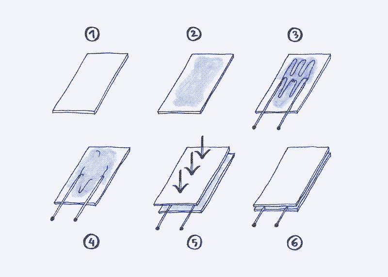
Assembly of the heating brick
-
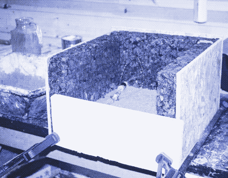
fig 1-2. Place one of the tiles with the back side facing up, apply a dollop of mortar, and flatten it across the tile, almost to the edges.
-
fig 3. Place the electric resistance circuit on top of the mortar. Make sure the wires don’t touch or cross, as this would create a short circuit. Try to evenly distribute the wire across the surface to distribute the heat evenly, but avoid the edges to prevent the nichrome wire from sticking out. Leave at least 3-5 cm of heat-resistant electric wire protruding from the tile on one side, so that you can solder or otherwise connect it to a standard electrical cable.
-
fig 4-6. Add a little bit of mortar on the other tile and press it on top of the other like a sandwich. Leave it to dry out for at least 48 hours.
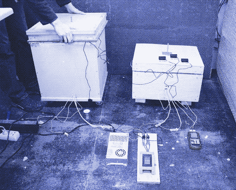
Setting up a test station for electric heating resistance heaters
A test station is convenient for testing resistance heating elements designed to operate on solar panels. Such a test station consists of a DC power supply and a buck or boost converter. It allows you to simulate the solar panel’s power output using grid power. A test station also serves to measure the precise resistance value of 1m of nichrome wire.
A 12V or 24V DC power supply converts 110/220-240V AC power into DC power, comparable to the electricity produced by a solar panel. Choose one with a capacity of at least the power output of your solar panel (100W in our case). If you connect a buck or boost converter to it, you can manipulate the 12V or 24V output voltage into a higher or a lower voltage. Since our heating resistance runs on a solar panel without a battery or charge controller (Vmax = 18V), you can match the buck or boost converter to an output of 18V.
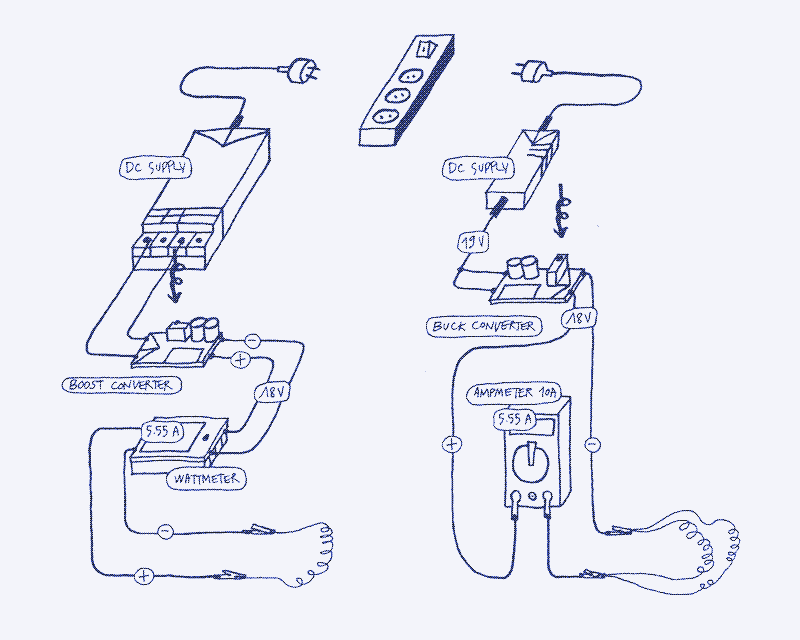
To wire it, connect a + and - cable to the DC supply into the buck or boost converter. Use a boost converter to step up the voltage from a DC supply below 18V, or a buck converter to lower he voltage drom a 24V power supply.
If you build an electric heating resistance that you want to run on a 12V or 24V battery, you only need the DC power supply (with a voltage output of 12 or 24V, respectively). You may also find a AC/DC converter with an 18V output, in which case there’s no need for a buck or boost converter.
If you are short on cash, you can use a laptop adapter instead of a DC power supply. The DC output of a laptop adapter is printed on the adapter itself. It’s typically around 70-90W at 19-20V. While it won’t be able to power a 100W solar cooker at full strength, it’s suitable for testing the circuit, and you can obtain it for free. If you have a lot of money, you can also purchase an adjustable lab DC supply, which allows you to adjust the voltage and current outputs using knobs.
Other types of power sources
In case you want to build a heating element that runs on a 12V or 24V battery and solar charge controller, the voltage value for your calculation is 12V or 24V, respectively. The current depends on the wattage that you want to achieve. For example, if you have a 12V power source and you want a 100W heating element, you need 8.33A. If you have a 24V power source and you want a 100W heating element, you need 4.17A.
Reactions
To make a comment, please send an e-mail to solar (at) lowtechmagazine (dot) com. Your e-mail address is not used for other purposes, and will be deleted after the comment is published. If you don’t want your real name to be published, sign the e-mail with the name you want to appear.
Reactions
Michael
Hi,
First of all, I would like to thank you for the website itself. I always find good ideas and inspiration here. Regarding the excellent article “How to Assemble an Electric Heating Element from Scratch,” I wanted to mention another possible application via a link to my own site: https://rz01.org/heated-trackball/ This quite brief and old post describes how to convert a trackball (or mouse) into a heated input device.
Best regards, Michael
Guillaume Jouvance
Hi !
Your article “How to build an electrically heating table !” is really interesting. Unfortunately I am struggling to find a cheap 12V carbon heating foil on internet. I only find this (link) 12v for reptile or 220V heating foil (link). I think it would be great to give a weblink on a shitty seller like amazon or aliexpress because it will help many other DIY builder like me.
Thank your for your help !
Guillaume Jouvance Lower tech builder
Kris De Decker
Hi Guillaume,
I use this brand: https://www.amazon.es/dp/B07TZP82P4?ref=ppx_yo2ov_dt_b_fed_asin_title
This link goes to a 24V heat film but they also have 12V and they are available in different widths and lengths.
Good luck and best regards Kris